Method of Deposition of a Wear Resistant DLC Layer

a technology of dlc layer and wear resistance, which is applied in the direction of chemical vapor deposition coating, vacuum evaporation coating, coating, etc., can solve the problems of large reduction of the growth rate of the layer, large reduction of the quantity and size of the macroparticle, and increase the roughness of the coating, etc., to achieve a reduced surface roughness, a reduced generation of macroparticles, and a higher hardness of the prepared layer

Active Publication Date: 2019-02-07
PLATIT
View PDF0 Cites 6 Cited by
  • Summary
  • Abstract
  • Description
  • Claims
  • Application Information

AI Technical Summary

Benefits of technology

[0015]A surprising and quite unexpected effect of the method based on the invention is that the cathode spot is accelerated by several orders, the steering of the cathode spot motion by a magnetic field being maintained.
[0017]It is advantageous if a rotary cylindrical cathode is used as the cathode.
[0018]The method in accordance with this invention provides the following advantages.
[0019]Since the cathode spot moves faster, the generation of macroparticles is reduced. This results in a reduced roughness of the coating.
[0021]Maintaining the cathode spot within the expected path is simpler as the speed of the cathode spot is considerably higher than the rotation speed of the cathode, which prevents the cathode spot from being forced out of its optimum path due to the rotation of the cathode. This leads to a higher stability of arc burning.
[0022]Another result of the method in accordance with the invention is a better uniformity of the prepared layers.

Problems solved by technology

Meunier; March 1997), which has an adverse impact on the quantity and size of macroparticles and consequently an increased coating roughness.
The problem of ta-C layers prepared with the use of the low-voltage arc consists of an extremely high roughness of the prepared coatings because the cathode spot moves very slowly (at a speed on the order of 1 cm / s) and it penetrates to a considerable depth of the cathode surface (approx.
The greatest disadvantage of this method is a considerable reduction of the growth rate of the layer.
A disadvantage of this method is that an expensive arc ignition technology (laser, magnetron) is required.
A disadvantage of this method is that the space where the arc burns is not precisely defined.

Method used


Image

  • Method of Deposition of a Wear Resistant DLC Layer
  • Method of Deposition of a Wear Resistant DLC Layer
  • Method of Deposition of a Wear Resistant DLC Layer

Examples


example 1

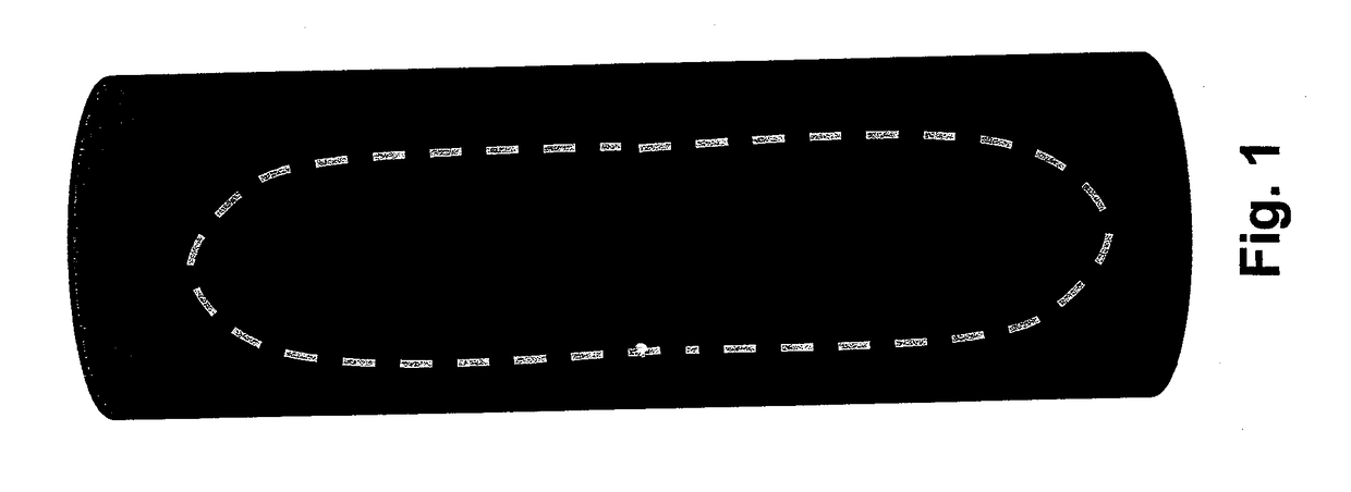
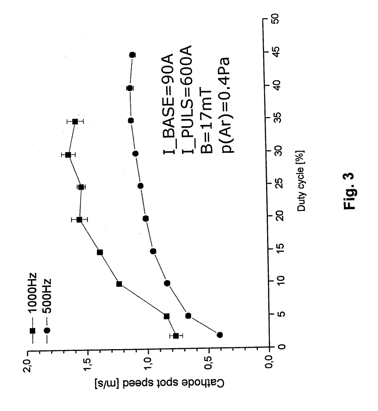
[0032]A polished sample made of tool steel having the dimensions of 15×15×5 mm was placed in a holder rotating around 3 axes on a substrate holder in a vacuum coating chamber. A central cylindrical rotary graphite cathode made of isostatically compressed graphite (glass graphite can also be preferably used) was positioned in the center of the vacuum chamber in the middle of the rotating substrates to be coated and was connected to a pulse source of low-voltage arc. The magnetic field intensity in the place of motion of the cathode spot was 17 mT. In the door of the vacuum chamber, a titanium cylindrical rotary cathode was placed that was connected to a low-voltage arc source. The chamber was evacuated to the pressure of 5×10⁻³ Pa.

[0033]Before the entire deposition of the DLC layer, the substrate was subjected to metal ion etching with Ti ions from the cathode for 10 min and after the end of the metal ion etching a Ti layer was applied for 5 min.

[0034]During the deposition of the DLC...

example 2

[0052]A polished sample made of tool steel having the dimensions of 15×15×5 mm was placed in a holder rotating around 3 axes on a substrate holder in a vacuum coating chamber. A central cylindrical rotary graphite cathode made of isostatically compressed graphite (glass graphite can also be preferably used) was positioned in the center of the vacuum chamber in the middle of the rotating substrates to be coated and was connected to a pulse source of low-voltage arc. The magnetic field intensity in the place of motion of the cathode spot was 17 mT. In the door of the vacuum chamber, a titanium cylindrical rotary cathode was placed that was connected to a low-voltage arc source. The chamber was evacuated to the pressure of 5×10⁻³ Pa.

[0053]Before the entire deposition of the DLC layer, the substrate was subjected to metal ion etching with Ti ions from the cathode for 10 min and after the end of the metal ion etching a Ti layer was applied for 5 min.

[0054]During the deposition of the DLC...

example 3

[0057]A polished sample made of sintered carbide having the dimensions of 15×15×5 mm was placed in a holder rotating around 3 axes on a substrate holder in a vacuum coating chamber. A central cylindrical rotary graphite cathode made of isostatically compressed graphite (glass graphite can also be preferably used) was positioned in the center of the vacuum chamber in the middle of the rotating substrates to be coated and was connected to a pulse source of low-voltage arc. The magnetic field intensity in the place of motion of the cathode spot was 17 mT. The chamber was evacuated to the pressure of 5×10⁻³ Pa.

[0058]Before the entire deposition of the DLC layer the samples were subjected to cleaning with glow discharge for 15 minutes.

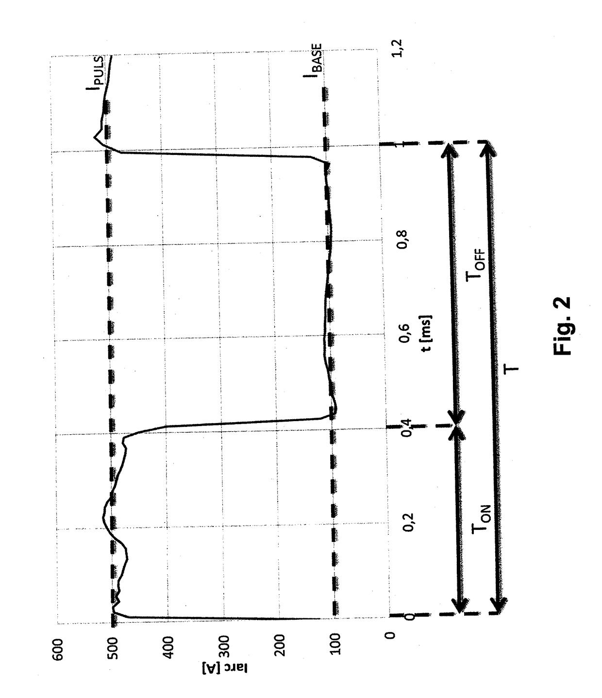
[0059]During the deposition of the DLC layer, the surface of the substrate was bombarded by carbon ions generated by the pulsed arc of the graphite cathode at the following parameters:

Holding current80ABias at the samples600VPulse current500APulsed arc freq...


PUM

PropertyMeasurementUnit
magnetic fieldaaaaaaaaaa
currentaaaaaaaaaa
currentaaaaaaaaaa

Abstract

A method of deposition of a wear resistant DLC layer onto substrates in a vacuum chamber from a graphite cathode by means of a low-voltage pulsed arc. Current pulses alternate with a holding current and a cathode spot moves on a surface of a graphite cathode. The motion of the cathode spot on the surface of the graphite cathode being steered by a magnetic field generated by a magnetic field source arranged under the surface of the graphite cathode. The value of the current pulses is 250 to 1000 A, the value of the holding current is 40 to 200 A, the frequency of the pulses is 100 to 5000 Hz and the pulse duty cycle is 1 to 90%, the intensity of the magnetic field in the place of the cathode spot being 5 to 40 mT.

Description

TECHNICAL FIELD[0001]The invention relates to a method of deposition of a wear resistant DLC layer onto substrates in a vacuum chamber from a graphite cathode by means of a low-voltage pulsed arc wherein current pulses alternate with a holding current and a cathode spot moves on a surface of a graphite cathode, the motion of the cathode spot on the surface of the graphite cathode being steered by a magnetic field generated by a magnetic field source arranged under the surface of the graphite cathode.PRIOR ART[0002]Various methods are used to apply wear resistant DLC (diamond like carbon) layers. Besides the CVD (chemical vapor deposition) methods these are mainly the physical vapor deposition methods abbreviated as PVD, which comprise of low voltage vacuum arc deposition magnetron sputtering (non-reactive or reactive) and plasma spraying.[0003]The low-voltage arc PVD technology can be used to prepare hard wear resistant layers of the DLC (diamond line carbon) type with a high conten...

Claims


Application Information

Patent Timeline
Patent Type & Authority Applications(United States)
IPC IPC(8): C23C14/06C23C14/02C23C14/32C23C16/26H01J37/32
CPCC23C14/0611H01J37/3266C23C14/022H01J37/32055C23C14/325C23C16/26C23C14/0605
Inventor JILEK, MOJMIR
Owner PLATIT
Why Eureka
Try Eureka