Monopole antenna

Active Publication Date: 2019-02-07
KIM MEE JEONG
View PDF0 Cites 5 Cited by
  • Summary
  • Abstract
  • Description
  • Claims
  • Application Information

AI Technical Summary

Benefits of technology

[0016]As described above, according to the monopole antenna of the present invention, an ultra-wideband antenna (UWB antenna) employing a quasi-Moebius strip and a via-hole structure can be miniaturized.
[0017]In other words, according to the present invention, a length of a physical circumference is reduced by 1/(N+1) times as compared with a conventional ring antenna. While a resonance frequency is generated per one rotation around a circumference, the present invention can obtain an ultra-wideband characteristic ranging from about 2 GHz to 10 GHz by employing the quasi-Moebius strip and the via-hole.
[0018]In addition, according to the present invention, a radiation pattern in a far-field exhibits omni-directional characteristics similar to a typical monopole antenna, and directivity can be controlled by adjusting a rotation angle of each ring provided in a radiator.
[0019]Further, according to the present invention, the resonance frequency and a ref

Problems solved by technology

Among the above schemes, since a resonance frequency is generated per one rotation around a circumference, the helical structure is not suitable for a scheme of miniaturizing an antenna having a single resonance frequency characteristic.
In addition, schemes of appl

Method used


Image

  • Monopole antenna
  • Monopole antenna
  • Monopole antenna

Examples


Example

BEST MODE

Mode for Invention

[0063]Hereinafter, a monopole antenna according to a preferred embodiment of the present invention will be described in detail with reference to the accompanying drawings.

[0064]1. Miniaturization of Monopole Antenna

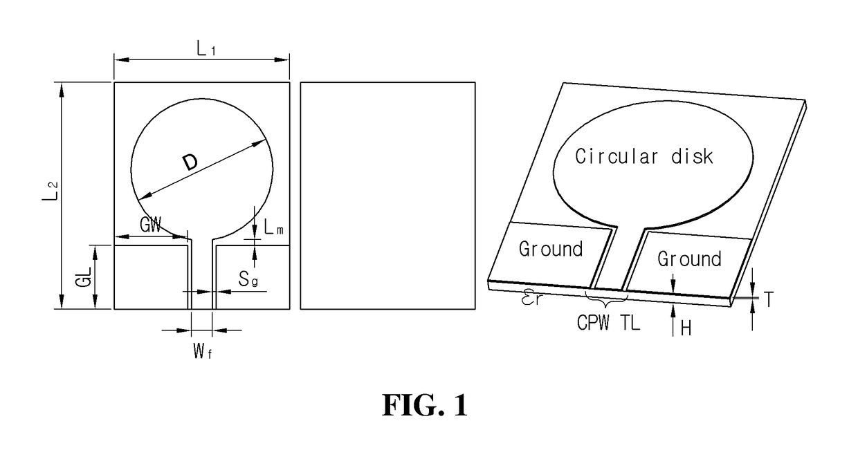
[0065]FIG. 1 is a block diagram showing a circular disc-shaped monopole antenna having a coplanar waveguide transmission line (hereinafter referred to as “CPW TL”) implemented on a dielectric substrate.

[0066]Electrical characteristics of the dielectric substrate are expressed by a dielectric constant εr of a dielectric, a dielectric thickness H, a copper foil thickness T, and a loss tangent value (tan δ). In this embodiment, the dielectric substrate a dielectric constant εr=2.2, a dielectric thickness H=30 mils (0.762 mm), a copper foil thickness T=0.5 oz. (0.018 mm), and a loss tangent value (tan δ)=0.001 (@ 5 GHz) is used.

[0067]In a coplanar waveguide line structure, as shown in FIG. 1, values of a slot width Sg and a center strip line width W...


PUM


Abstract

The present invention relates to a monopole antenna comprising: a radiator arranged in the center of a front surface of a dielectric substrate, and including a plurality of loops formed in a structure in which a Mobius strip is cut at least one time along the circumference; a first bridge for sequentially connecting one end of each loop; and a second bridge for connecting via-holes respectively formed at one end of the innermost loop and the outermost loop, thereby obtaining an effect of enabling an antenna, to which a quasi-Mobius strip and a via-hole structure are applied, to be miniaturized.

Description

TECHNICAL FIELD[0001]The present invention relates to a monopole antenna, and more particularly, to a monopole antenna applicable to a wireless communication system.BACKGROUND ART[0002]As wireless mobile communications evolve rapidly, various wireless communication systems such as 4G / 5G mobile communication terminals, wireless control systems, Machine to Machine (M2M), and Internet of Things (IoT) require elements which are more lightweight, have a simple structure, and are miniaturized into a structure that facilitates integration.[0003]Accordingly, various schemes for reducing a physical size of a circuit have been studied, and flat microwave elements and circuits have been widely developed and applied because they are easy to design and manufacture.[0004]In particular, manufacturers of mobile communication terminals and wireless control systems in the world require a miniaturized, flexible, broadband, high-gain antenna which is operated at a low power with high radiation efficien...

Claims


Application Information

Patent Timeline
IPC IPC(8): H01Q1/38H01Q3/01H01Q3/26H01Q7/00H01Q9/16H01Q9/40
CPCH01Q1/38H01Q3/01H01Q3/26H01Q7/00H01Q9/16H01Q9/40H01Q1/36H01Q9/27H01Q21/28
Inventor KIM, MEE JEONG
Owner KIM MEE JEONG
Why Eureka
Try Eureka