
Device and method for acquiring a particle present in a sample

a technology of biological particles and devices, applied in the field of optical acquisition of biological particles, can solve the problems of inability to observe bacteria in visualization mode, particularly long and complex marking process, and inability to achieve the above-mentioned identification methods, so as to improve the rapidity of treatment of patients, reduce acquisition time, and simplify measurement instruments

Active Publication Date: 2019-03-21
BIOMERIEUX SA +1
View PDF0 Cites 5 Cited by
  • Summary
  • Abstract
  • Description
  • Claims
  • Application Information

AI Technical Summary

Benefits of technology

The patent simplifies measurement instruments by not requiring highly-accurate focusing devices to focus images of particles. This reduces the acquisition time and the need for focusing or marking. The patent also describes a method to efficiently determine a focused matrix of a particle by averaging the particle's detection and specific focusing onto it.

Problems solved by technology

However, the marking process is particularly long and complex to implement and such chemical markers have a cytotoxic effect on bacteria.
As a result, such a visualization mode does not enable to observe the bacteria at several times of the culture of the bacteria.
The above-mentioned identification methods are however complex since they require a focusing in successive planes of focus.
On the contrary, the focusing in a single plane of focus, in other words at a single depth of analysis, is generally not sufficient to identify a type of microorganism with a low false detection rate.
The objective technical problem of the present disclosure is accordingly to observe a biological particle while limiting the acquisition time, that is, with no marking and with no accurate focusing of the optical system.

Method used


Image

  • Device and method for acquiring a particle present in a sample
  • Device and method for acquiring a particle present in a sample
  • Device and method for acquiring a particle present in a sample

Examples


Embodiment Construction

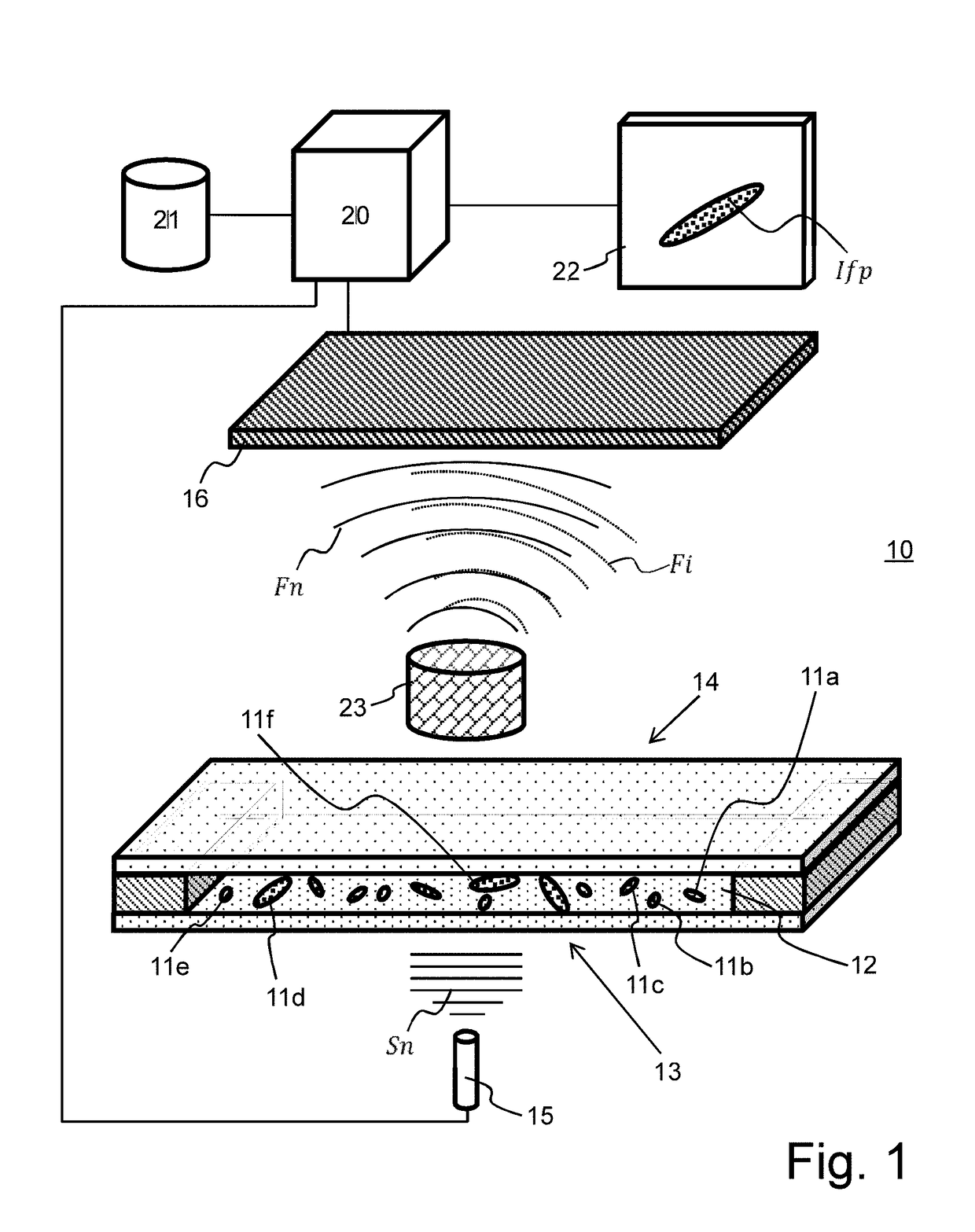
[0096]FIG. 1 illustrates a device 10 for observing a particle 11a-11f present in a sample 12. Sample 12 is arranged between a light source 15 which is spatially and temporally coherent (for example a laser) or pseudo-coherent (for example, a light-emitting diode, a laser diode), and a digital sensor 16 sensitive in the spectral range of the light source. Preferably, light source 15 comprises a small spectral width, for example, smaller than 200 nm, smaller than 100 nm, or smaller than 25 nm. In the following, reference is made to the central emission wavelength of the light source, for example, in the visible range. Light source 15 emits a coherent signal Sn directed towards a first surface 13 of the sample, for example, conveyed by a waveguide such as an optical fiber.

[0097]Sample 12 is a liquid such as water, a buffer solution, a culture medium or a reactive medium (comprising or not an antibiotic), containing the particles 11a-11f to be observed.

[0098]As a variation, sample 12 ma...


PUM


Abstract

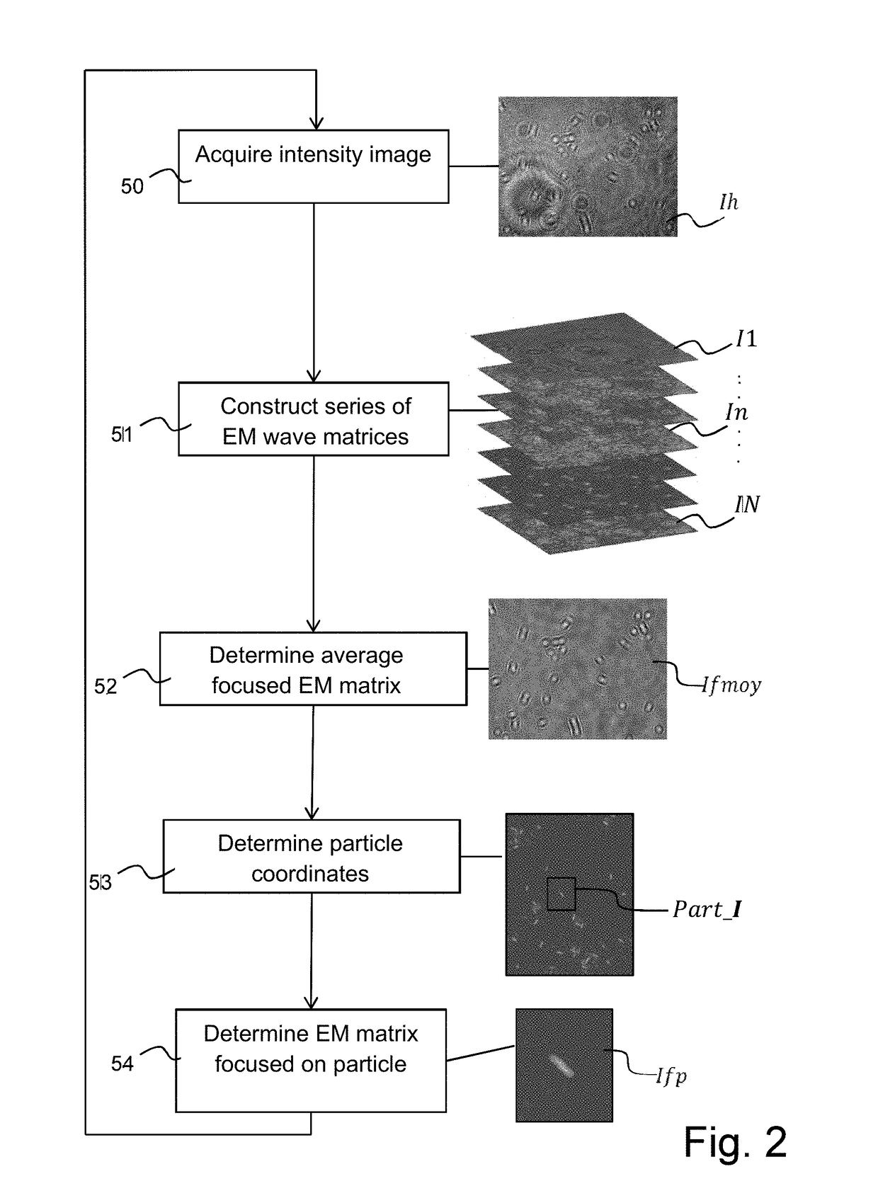
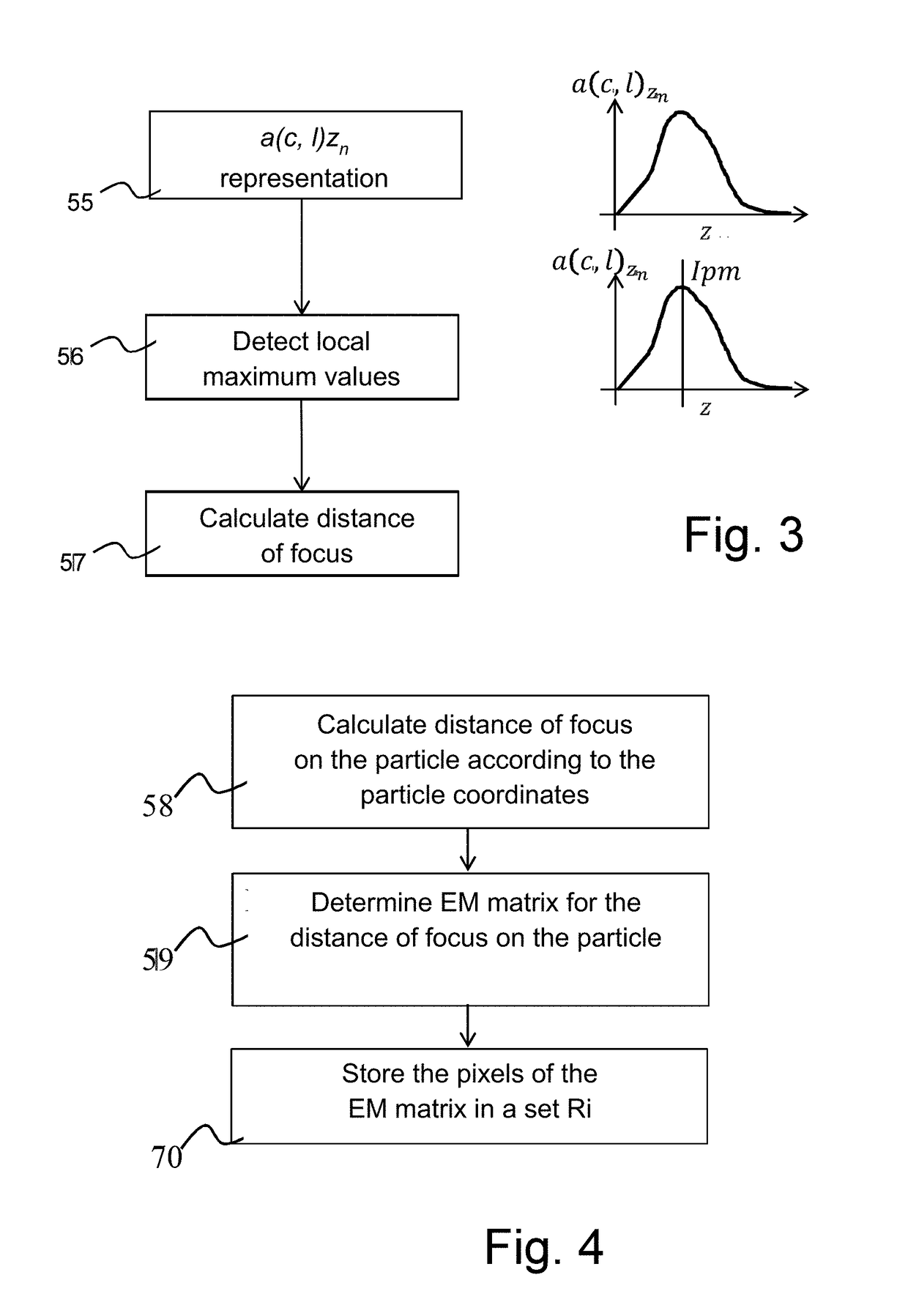
A device for acquisition of particles present in a sample includes a spatially coherent light source, an optical system, and an image sensor placed in the focal plane of the optical system. The image sensor is configured to capture an intensity image. A computational unit of the device is configured to construct a series of electromagnetic propagation matrices obtained for a plurality of defocusing offsets relative to a plane of focus of the optics. The computational unit is also configured to determine a first average focused electromagnetic matrix for the particles from the series of electromagnetic matrices, identifying at least one of the particles in the first electromagnetic matrix and storing the coordinates of said particle, and determining a second electromagnetic matrix at a distance of focus on a particle identified from the components of the series of electromagnetic matrices having the stored coordinates.

Description

TECHNICAL BACKGROUND[0001]The present disclosure relates to the field of optical acquisition of biological particles. The biological particles may be microorganisms such as bacteria, fungi, or yeasts, for example. They may also be cells, multicellular organisms, or any other particle of contaminating particle type, dust.[0002]The disclosed embodiments particularly advantageously apply to analyze the state of a biological particle, for example, to know the metabolic state of a bacterium after the application of an antibiotic. The disclosed embodiments for example enable to form an antibiogram of a bacterium.BACKGROUND OF THE DISCLOSURE[0003]An antibiogram is a laboratory technique aiming at testing the phenotype of a bacterial strain with respect to one or a plurality of antibiotics. An antibiogram is conventionally formed by culture of a sample containing bacteria and an antibiotic.[0004]European patent application Nº2 603 601 describes a method of forming an antibiogram by visualiz...

Claims


Application Information

Patent Timeline
IPC IPC(8): G03H1/08G01N15/14C12Q1/20G03H1/04
CPCG03H1/0866G01N15/1468C12Q1/20G03H1/0443G03H1/041G01N2015/1006G01N2015/1454G03H2001/0452G01N21/453G03H2001/0447G06T7/97G06T7/55
Inventor DOUET, ALICEJOSSO, QUENTIN
Owner BIOMERIEUX SA
Learn More