Laser Measuring Method And Laser Measuring Instrument

a laser measuring and laser diode technology, applied in the field of laser measuring methods and laser measuring instruments, can solve the problems of limited radiation output of laser diodes emitting pulsed laser beams, increase in the diameter of objective lenses, and increase in the size of measuring instruments, so as to prolong the life of light emitters, reduce manufacturing costs, and reduce the duty ratio of light emitters

Active Publication Date: 2019-03-28
KK TOPCON
View PDF0 Cites 9 Cited by
  • Summary
  • Abstract
  • Description
  • Claims
  • Application Information

AI Technical Summary

Benefits of technology

[0023]According to the present invention, in the laser measuring method, a scanning is performed while irradiating a pulsed distance measuring light to a measuring point, a reflected distance measuring light from the measuring point is received, a reciprocating time per pulsed light of the pulsed distance measuring light is detected with respect to the measuring point, and a distance measurement is performed based on the reciprocating time, comprising steps of setting a scanning speed and a light emission cycle of the pulsed light such that the measuring point is multiply irradiated with the pulsed light by two or more times within a time when the pulsed light passes the measuring point, integrating light receiving signals acquired by multiply irradiating the pulsed light by two or more times and carrying out the distance measurement based on the integrated light receiving signals. As a result, the distance measurement, is possible under a condition where a light amount of the reflected distance measuring light per one pulsed light is small, a long distance measurement becomes possible, a duty ratio of a light emitter can be reduced, and it is possible to contribute to a reduction of a manufacturing cost and a prolongation of a life of the light emitter.
[0024]Further, according to the present invention, the laser measuring instrument comprises a light emitter for pulse-emitting a distance measuring light, a driver for making the light emitter emit, a scanning unit for scanning while irradiating the distance measuring light, a light receiving signal processing module for receiving a reflected distance measuring light from a measuring point, detecting a reciprocating time per pulsed light of the distance measuring light with respect to the measuring point, and performing a distance measurement based on the reciprocating time, and a timing generating circuit for issuing a timing signal for controlling a light emission timing of the light emitter and a timing signal for controlling a detection timing of the reflected distance measuring light, wherein the timing generating circuit is configured to input a timing signal for pulse-emitting the light emitter in a short cycle and a timing signal for pausing a light emission to the driver, the driver is configured to make the light emitter pulse-emit according to the timing signals from the timing generating circuit, a light emission time interval in the short cycle is set such that the measuring point is multiply irradiated with the pulsed light by two or more times within a time when the pulsed light passes the measuring point, and the light receiving signal processing module is configured to integrate light receiving signals acquired by multiply irradiating the pulsed light by two or more times and to carry out the distance measurement based on the integrated light receiving signals. As a result, the distance measurement is possible under the condition where the light amount of the reflected distance measuring light per one pulsed light is small, a long distance measurement becomes possible, a duty ratio of a light emitter can be reduced, and it is possible to contribute to a reduction of a manufacturing cost and a prolongation of a life of a light emitter.

Problems solved by technology

However, the increase in the diameter of the objective lens is accompanied with a size increase and a weight increase in a measuring instrument, and a radiation output of a laser diode emitting the pulsed laser beam is also limited.

Method used


Image

  • Laser Measuring Method And Laser Measuring Instrument
  • Laser Measuring Method And Laser Measuring Instrument
  • Laser Measuring Method And Laser Measuring Instrument

Examples


first embodiment

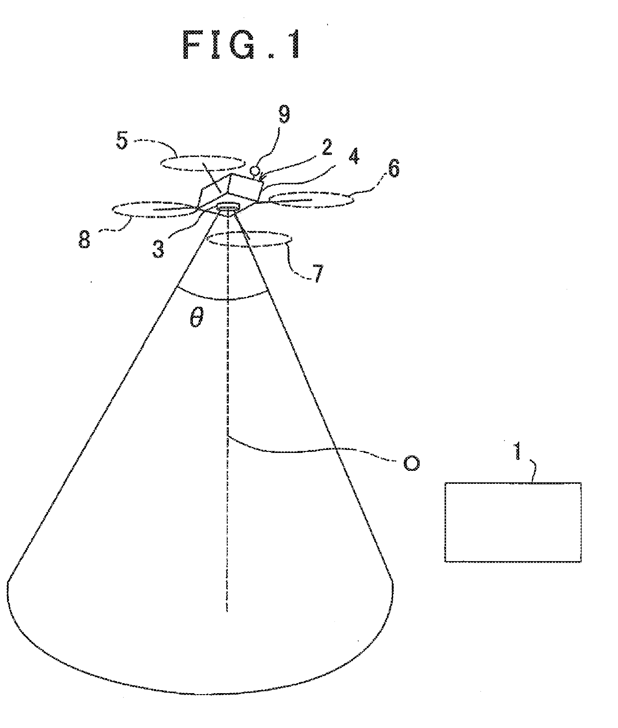
[0049]First, a description will be given on general features of the first embodiment by referring to FIG. 1 and FIG. 2.

[0050]In FIG. 1, reference numeral 1 denotes a base station control device 1 installed on the ground, and the base station control device 1 is capable of data communication with an unmanned aerial vehicle 2 and a laser scanner 3 and executes a control of a flight of the unmanned aerial vehicle 2, a setting and a change of a flight plan. Further, the base station control device 1 executes a collection, a storage and a management of a measurement result obtained by the laser scanner 3 and a preparation of a topographic map or the like based on the measurement result.

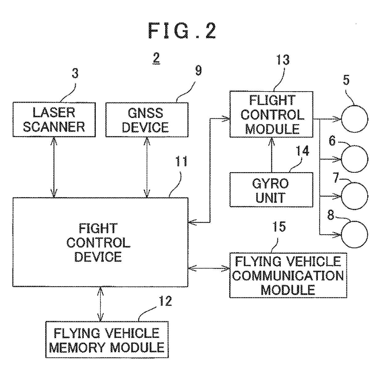
[0051]The unmanned aerial vehicle 2 has an airframe 4 and has two or more propeller units provided on the airframe 4, for instance, four sets of front, rear, right and left propeller units 5, 6, 7 and 8, and the propeller units 5, 6, 7 and 8 individually comprise motors, respectively, and a driving of each...

second embodiment

[0158]In the second embodiment, timing signals for a light emission is issued from timing generating circuits 81a, 81b and 81c to drivers 82a, 82b and82c at the same time, and the light emitters 41a, 41b and 41c are emitted at the same timing by the drivers 82a, 82b and 82c.

[0159]In a light emission mode of each of the light emitters 41a, 41b and 41c, similarly to the above, a pulsed light is emitted in a long cycle including a pulsed light emission in a short cycle, and in the pulsed light emission in the short, cycle, the pulsed light is multiply irradiated with respect to the measuring points Pa, Pb and Pc. It is to be noted that since a processing of light receiving signals acquired by a multiple irradiation is similar to the embodiment as described above, a description thereof will be omitted.

[0160]FIG. 16 shows a light emission timing of each of the distance measuring lights 46a, 46b and 46c. Further, rectangular waves 91a, 91b and 91c in each of the distance measuring lights...

third embodiment

[0167]FIG. 18 shows a relationship between a scanning locus of each of the distance measuring lights 46a, 46b and 46c and the measuring points Pa, Pb and Pc in the There is a time deviation in the light emission timing of the light emitters 41a, 41b and 41c, the laser scanner 3 is mounted on an unmanned aerial vehicle 2, and the unmanned aerial vehicle 2 is flying. Therefore, a position measured by each of the distance measuring lights 46a, 46b and 46c is displaced for the time difference of the light emission timing.

[0168]On the other hand, a measuring timing of the distance measuring lights 46a, 46b and 46c extremely faster than a flying speed of the unmanned aerial vehicle 2. Further, a moving amount of the unmanned aerial vehicle 2 corresponding to the time deviation in the light emission timing of the light emitters 41a, 41b and 41c becomes extremely small, and an effect of a substantially simultaneous measurement can be obtained.

[0169]FIG. 19 shows the light emission timing o...


PUM


Abstract

A laser measuring instrument comprises a light emitter, a driver, a scanning unit, a light receiving signal processing module for detecting a reciprocating time per pulsed light of a distance measuring light and performing a distance measurement, and a timing generating circuit for issuing a timing signal, wherein the timing generating circuit is configured to issue a timing signal for making the light emitter pulse-emit in a short cycle and a timing signal for pausing a light emission, the driver is configured to make the light emitter pulse-emit according to the timing signals, a light emission time interval in the short cycle is set such that a measuring point is multiply irradiated with the pulsed light by two or more times within a time when the pulsed light passes the measuring point, and the light receiving signal processing module is configured to integrate acquired light receiving signals and to carry out the distance measurement.

Description

BACKGROUND OF THE INVENTION[0001]The present invention relates to a laser measuring method and a laser measuring instrument using a pulsed laser beam as a distance measuring light.[0002]In a laser measuring method using a pulsed laser beam as a distance measuring light, the pulsed laser beam is irradiated to an object to be measured, a reflected light is received, a reciprocating time of the pulsed laser beam is detected, and a distance to the object to be measured is determined. Further, point cloud data is also acquired by moving the distance measuring light with respect to the object to be measured (scanned) and by measuring the distance per pulse.[0003]In order that a distance measurement per pulse is enabled and a measurement accuracy is ensured, a predetermined light receiving amount is required, but the light receiving amount is attenuated or a luminous flux is scattered when the pulsed laser beam is reflected by the object to be measured, and the light receiving amount decre...

Claims


Application Information

Patent Timeline
Patent Type & Authority Applications(United States)
IPC IPC(8): G01S17/08G01C5/00G01S17/02H01S3/0941G01S17/66G01S17/89G02B5/04B64C39/02G01S17/86
CPCG01S17/08G01C5/005G01S17/023H01S3/0941G01S17/66G01S17/89G02B5/04B64C39/024H04N5/2257B64C2201/14G01S17/42G01S7/4808G01S7/4815G01S7/4817G01S7/4818G01S17/86H04N23/57B64U2201/00
Inventor OHTOMO, FUMIOKUMAGAI, KAORUYOSHINO, KEN-ICHIRO
Owner KK TOPCON
Why Eureka
Try Eureka