
Systems and methods for management of cryogenic storage vessels

a technology for cryogenic storage vessels and management methods, applied in the direction of container discharge methods, container filling under pressure, instruments, etc., can solve the problems of affecting the reliability of the overall system, affecting the ability of the controller to maintain an acceptable level, and inability to detect the level sensor

Inactive Publication Date: 2019-04-04
IC BIOMEDICAL US LLC
View PDF0 Cites 7 Cited by
  • Summary
  • Abstract
  • Description
  • Claims
  • Application Information

AI Technical Summary

Benefits of technology

This patent describes a cryogenic storage system that includes a vessel for holding a cryogenic liquid and two levels of measurement to ensure the liquid level is always known. The system also includes a controller that uses the level measurements to control the filling of the storage vessel. The technical effect of this invention is to provide a more reliable and efficient way to store cryogenic items in a safe and secure way.

Problems solved by technology

A weakness of existing systems centers on the single point of failure associated with the control scheme described above.
In particular, there is an inherent risk associated with failure of the level sensor.
Such failure would inhibit the controller's ability to maintain an acceptable LN2 level.
Although other parameters, such as temperature, can be monitored in existing systems and a local alarm can issue if a problem develops, the single point of failure associated with the level sensor weakens reliability of the overall system.
Conventional liquid nitrogen freezers, however, have an inherent operational risk associated with an inability to measure and communicate a vacuum integrity of a freezer, once put into service.
Nitrogen gas displaces oxygen, which potentially creates a hazardous environment for any person in the vicinity of a freezer being filled.
A freezer in a closed space presents an even greater hazard.

Method used


Image

  • Systems and methods for management of cryogenic storage vessels
  • Systems and methods for management of cryogenic storage vessels
  • Systems and methods for management of cryogenic storage vessels

Examples


Embodiment Construction

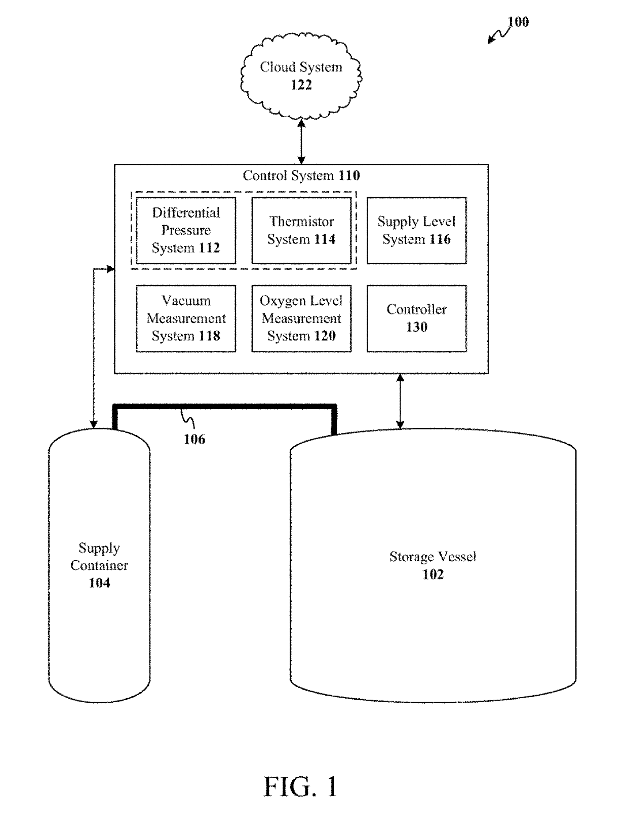
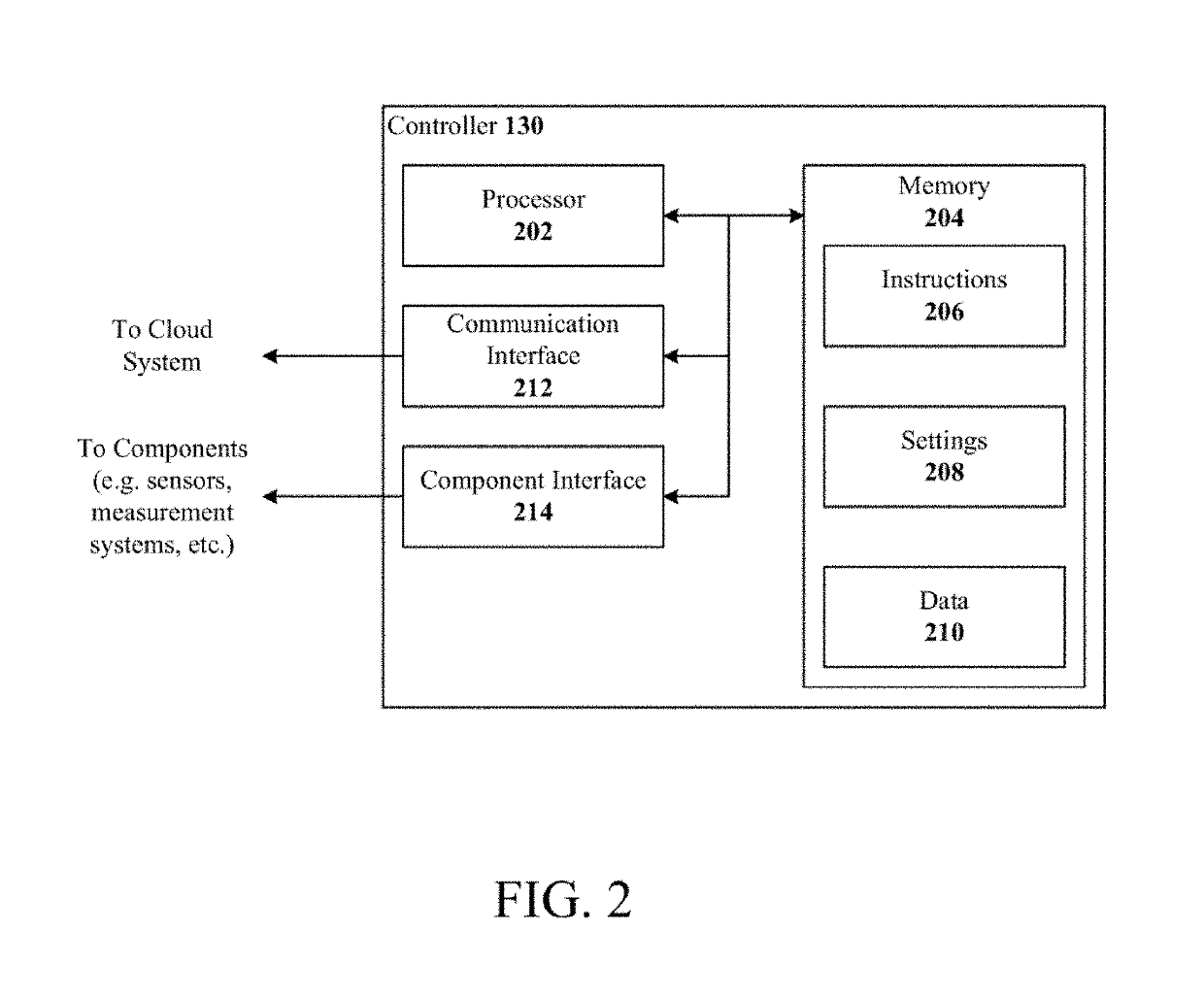
[0032]In liquid nitrogen (LN2) freezers, maintaining appropriate temperatures is vital to the safety and viability of stored products (e.g. samples). Sample safety and user safety is greatly improved with application of various techniques, individually or jointly, with LN2 freezers to mitigate risks associated with single points of failure. These techniques include utilizing a dual level sensing system, acquiring data related to vacuum integrity and temperature profile, communicating with supply cylinders, obtaining information on oxygen levels, and transmitting operational data to a cloud-based platform that performs analytics and enables a sophisticated notification system.

[0033]A dual level sensing system provides an enhanced LN2 level measurement that includes all advantages of conventional level measurement systems (e.g. singular differential pressure (DP) sensors, negative temperature coefficient (NTC) thermal resistors or thermistors, capacitance probes, superconductivity res...


PUM


Abstract

Dual level sensing, vacuum monitoring, smart supply cylinders, smart oxygen monitors, and real time data collection functionality are integrated with a cryogenic storage system to improve sample safety and user safety. The dual level sensing system includes two liquid nitrogen level sensors installed into a cryogenic freezer that send redundant level information to a controller. Vacuum monitoring is performed via a gauge, installed on a vacuum port, that communicates data to the controller. The controller further receives level information from supply cylinders and oxygen levels from one or more oxygen monitors. The aforementioned data sources can be integrated into control decisions executed by the controller. In addition, all operational data of the cryogenic storage system is communicated to a cloud-based platform to provide real-time status monitoring, trend analysis, and alarm notifications.

Description

CROSS-REFERENCE TO RELATED APPLICATIONS[0001]This application claims the benefit of and priority to U.S. Provisional Application No. 62 / 566,900, filed on Oct. 2, 2017. The entirety of this application is incorporated by reference.TECHNICAL FIELD[0002]In general, the present invention relates to cryogenic storage vessels and, in particular, to sensor systems, control systems, and a cloud-based platform to facilitate improved operation and maintenance of the storage vessels.BACKGROUND OF THE INVENTION[0003]Liquid nitrogen freezers with electronic control systems can provide automatic filling operations. Typical operation involves a START FILL parameter and a STOP FILL parameter established in a controller. When a level of liquid nitrogen (LN2) in the freezer falls below a level specified by the START FILL parameter, the controller opens a cryogenic solenoid valve to allow LN2 to flow into the freezer. When the level of LN2 inside the freezer reaches a level set for the STOP FILL param...

Claims


Application Information

Patent Timeline
IPC IPC(8): F17C5/00F17C13/02F17C5/02F17C13/00
CPCF17C5/002F17C13/025F17C5/02F17C13/001G01F23/247F17C2201/0109F17C2221/014F17C2223/0161F17C2250/032F17C2250/036F17C2250/0417F17C2250/0434F17C2250/0452F17C2250/034F17C3/04F17C3/08F17C13/02F17C13/026F17C2203/032F17C2203/0391F17C2203/0629F17C2250/0491F17C2250/0495F17C2250/0636F17C2250/075F17C2250/077F17C2260/024F17C2270/0509Y02E60/32
Inventor ROMANOS, JOHN L.OEFF, KEVIN M.
Owner IC BIOMEDICAL US LLC
Learn More