
Solar selective coating

Active Publication Date: 2019-05-02
POLYCSP APS
View PDF0 Cites 0 Cited by
  • Summary
  • Abstract
  • Description
  • Claims
  • Application Information

AI Technical Summary

Benefits of technology

The patent text describes a coating system that has high resistance to corrosion, meaning that any small damage in the outer layers of the coating will not lead to larger areas of corrosion. This results in reduced costs for production facilities, as the system uses a small magnetron and plasma region compared to the size of the workpiece.

Problems solved by technology

One challenge is to produce solar absorbers for thermal solar collector systems typically comprising several-meter-long absorber means to be coated under vacuum conditions.
Another challenge is to achieve state of the art solar selective coatings which optical properties are long-term stable at high temperatures and in atmospheric environment.
Long term use of solar absorbers shows that the substrate surface even when coated with a thin surface layer is subject to corrosion.
Furthermore, the solar selective coating may be subject to deterioration and migration from the substrate to the different layers of the coating resulting in changed optical properties of the solar selective coating.
Thus, yet another challenge is to increase the long-term stability of the solar absorbers to prolong the lifespan by reducing surface corrosion and deterioration of the optical properties to a few percentage change over a lifespan of up to 25 years when used at high temperatures and in atmospheric conditions.
These familiar vacuum tubes suffer the characteristic problems of lack of robustness and longevity.
However, the more layers comprised in the coating the more complicated becomes both the process and method of making the coating.
As German Patent Application DE 10 2013 112 532 A1 provides, the configuration of a layer stack or a layer structure with the desired physical properties can be arbitrarily complex and cannot be predictable, or it can be very difficult to predict.

Method used


Image

  • Solar selective coating
  • Solar selective coating
  • Solar selective coating

Examples


Embodiment Construction

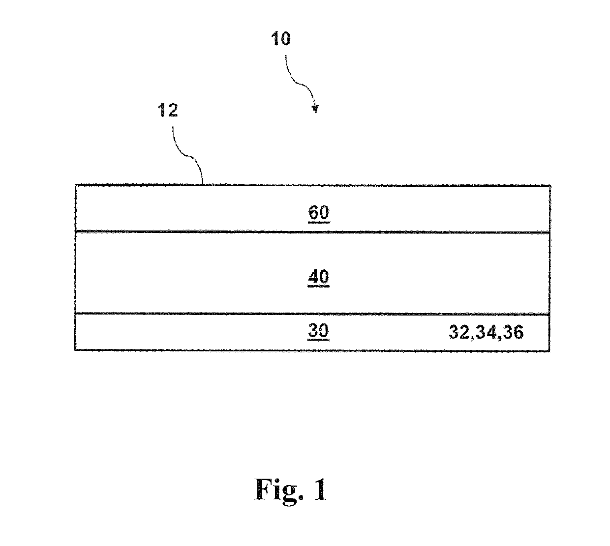
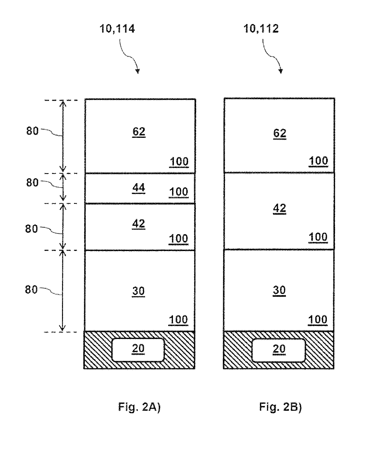
[0016]One such exemplary object of the present disclosure can be achieved by providing an exemplary solar selective coating to be deposited on a substrate according to an exemplary embodiment of the present disclosure. For example, such exemplary solar selective coating can comprise an adhesion layer, an absorber stack comprising at least one absorber layer, and an antireflection stack comprising at least one antireflection layer in a sandwich construction. The exemplary sandwich construction can be configured with, e.g., the adhesion layer deposited onto the substrate, the absorber stack deposited on the adhesion layer, and the antireflection stack deposited on the absorber stack. The exemplary adhesion layer can comprise a metallic layer comprising a refractory metal and a dope-material, whereas the exemplary dope-material can comprise a metal or metalloid and which metallic layer is configured with an amorphous disordered structure.

[0017]In an exemplary embodiment of the present ...


PUM

PropertyMeasurementUnit
Temperatureaaaaaaaaaa
Fractionaaaaaaaaaa

Abstract

An exemplary solar selective coating can be provided to be deposited on a substrate. The exemplary solar selective coating can comprise an adhesion layer, an absorber stack comprising at least one absorber layer, and an antireflection stack which can comprise at least one antireflection layer, e.g., all provided in a sandwich configuration. The sandwich configuration can provide the adhesion layer deposited onto the substrate, the absorber stack deposited on the adhesion layer, and the antireflection stack deposited on the absorber stack. The adhesion layer can comprise a metallic layer comprising molybdenum and titanium.

Description

CROSS REFERENCE TO RELATED APPLICATION(S)[0001]This application relates to, and claims the benefit and priority from International Patent Application No. PCT / DK2017 / 050060 filed on Mar. 3, 2017 that published as International Patent Publication No. WO 2017 / 162247 on Sep. 28, 2017, which claims the benefit and priority from European Patent Application No. 16161630.5 filed on Mar. 22, 2016, the entire disclosures of which are incorporated herein by reference in their entireties.FIELD OF THE DISCLOSURE[0002]The present disclosure relates to an exemplary solar selective coating to be deposited on a substrate, whereas the exemplary solar selective coating can comprise an adhesion layer, an absorber stack comprising at least one absorber layer, and an antireflection stack comprising at least one antireflection layer in a sandwich construction. The exemplary sandwich construction can be configured with, e.g., the adhesion layer deposited onto the substrate, the absorber stack deposited on ...

Claims


Application Information

Patent Timeline
IPC IPC(8): F24S70/20F24S10/70F24S40/40F24S70/25F24S70/30F24S70/65
CPCF24S70/20F24S10/70F24S40/40F24S70/25F24S70/30F24S70/65F24S2080/011F24S2080/03F24S70/225Y02E10/44Y02E10/40
Inventor LARSEN, JENS WILLIAM
Owner POLYCSP APS
Learn More