Smelting process and apparatus

Active Publication Date: 2019-05-09
TATA STEEL
View PDF0 Cites 1 Cited by
  • Summary
  • Abstract
  • Description
  • Claims
  • Application Information

AI Technical Summary

Benefits of technology

The present invention improves the performance of heat pipes used in smelting vessels to reduce the risk of uncontrolled release of heat transfer fluid, which can cause operational and safety issues. The invention minimizes this risk by using a vent that allows vapor to escape while retaining the liquid phase in the heat pipe or progressively vaporizing it. This helps to control the pressure and temperature within the heat pipe and prevents failure.

Problems solved by technology

By way of example, the applicant found that heat pipe failure is a potential issue near the end of the operational design life of a heat pipe when the pipe has been under too much heat load for too long a time period.

Method used


Image

  • Smelting process and apparatus
  • Smelting process and apparatus
  • Smelting process and apparatus

Examples


Embodiment Construction

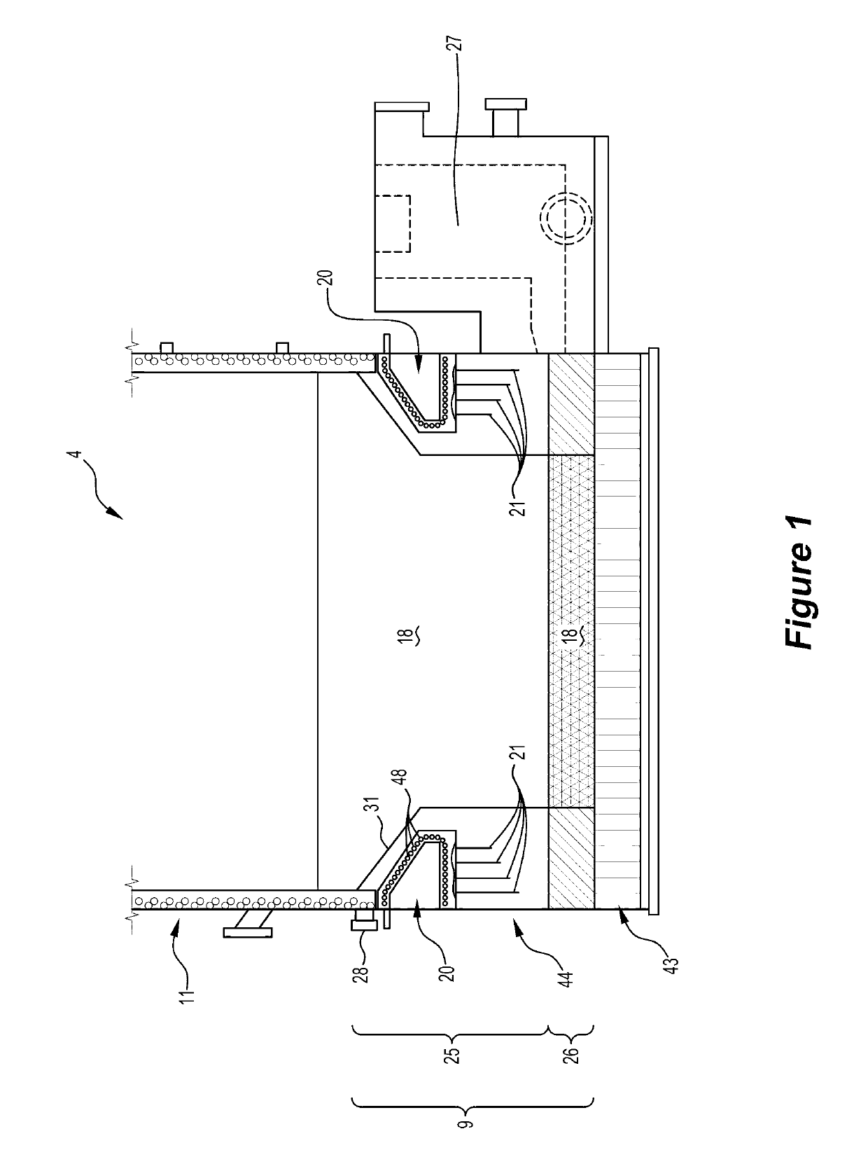
[0100]The invention is relevant to the direct smelting vessels that are used in HIsarna and HIsmelt plants. The invention is not confined to direct smelting vessels used in these plants and is relevant to any suitable direct smelting vessel that contains a molten bath that includes a molten metal layer and a molten slag layer and has a refractory material-lined hearth that requires cooling to maximise the operational life of the hearth, more specifically to reduce refractory wear of the refractory material of the hearth due to contact with molten material in the form of molten slag or molten metal.

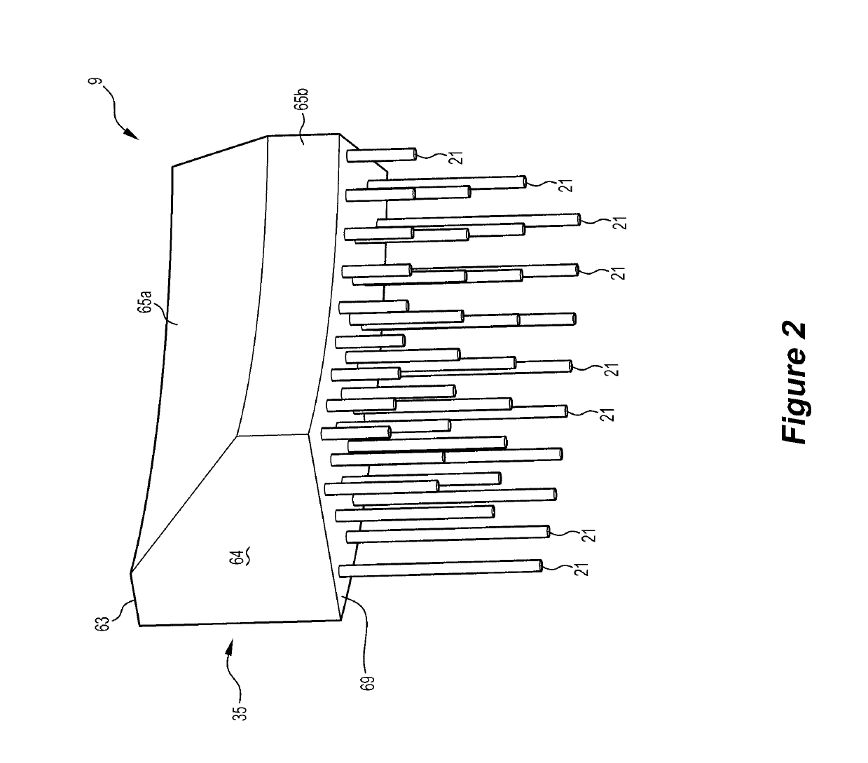
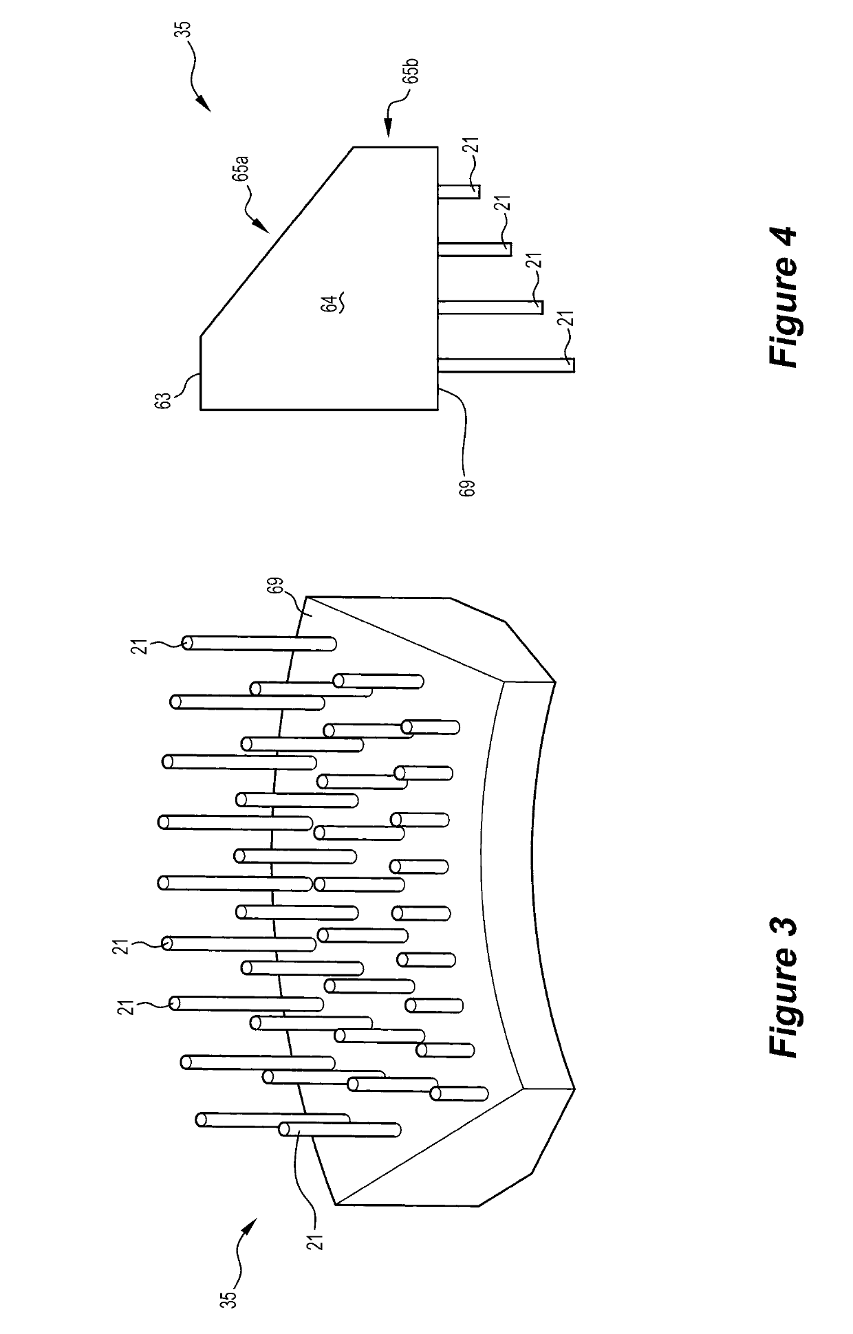
[0101]The Figures show a part of a direct smelting vessel 4 that is in accordance with an embodiment of the invention. The smelting vessel 4 is suitable for HIsarna and HIsmelt plants and is of the type disclosed in the above-mentioned International publication WO 2015 / 081376 in the name of the applicant. The smelting vessel 4 comprises a hearth generally identified by the numeral 9 in FIG...


PUM

PropertyMeasurementUnit
Temperatureaaaaaaaaaa
Pressureaaaaaaaaaa

Abstract

A smelting vessel includes a plurality of heat pipes (21) positioned in a refractory lining of at least a part of the hearth (9) for cooling at least a part of the refractory lining. At least one of the heat pipes includes (a) a liquid phase of a heat transfer fluid, typically water, in a lower section of the heat pipe and (b) a vapor phase of the heat transfer fluid, typically steam, in an upper section of the heat pipe. The heat pipe also includes a vent to allow vapour phase to escape from the heat pipe to reduce the pressure or the temperature within the heat pipe when the vapour pressure or the temperature in the heat pipe exceeds a predetermined threshold pressure or temperature.

Description

TECHNICAL FIELD[0001]The present invention relates to a process and an apparatus for direct smelting a metalliferous material such as an iron-containing material (such as an iron ore) or a titania slag or a copper-containing material.[0002]The present invention relates particularly to smelting a metalliferous material in a direct smelting vessel that contains a molten bath having a molten metal layer and a molten slag layer and has a refractory material-lined hearth that requires cooling to maximise the operational life of the hearth. The present invention relates particularly to cooling the refractory material-lined hearth of the direct smelting vessel to maximise the operational life of the hearth.BACKGROUND[0003]There are a number of known molten bath-based smelting processes.[0004]One molten bath-based smelting process that is generally referred to as the “HIsmelt” process is described in a considerable number of patents and patent applications in the name of the applicant.[0005...

Claims


Application Information

Patent Timeline
IPC IPC(8): C21B7/10C21B7/06F27D1/12F28D15/02
CPCC21B7/10C21B7/06F27D1/12F28D15/0275F27B2014/002F27B2014/0837F27B2014/104C21B7/12F27B3/24C21B7/106C21C5/4646F28D2021/0057F28F2265/12C21B13/00F27B1/24
Inventor PILOTE, JACQUESDRY, RODNEY JAMES
Owner TATA STEEL
Why Eureka
Try Eureka