
Method and system for fault positioning and recovery of voltage source converter

Active Publication Date: 2019-05-09
NR ELECTRIC CO LTD +1
View PDF0 Cites 4 Cited by
  • Summary
  • Abstract
  • Description
  • Claims
  • Application Information

AI Technical Summary

Benefits of technology

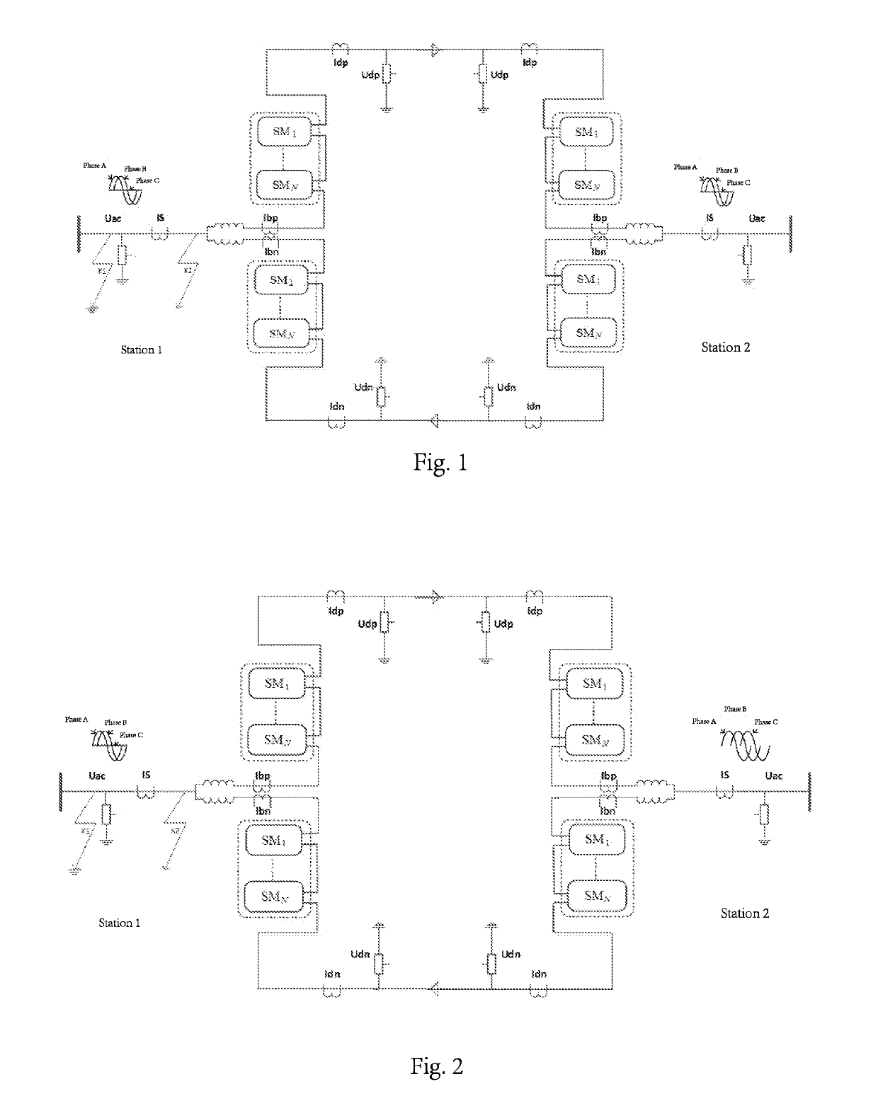
The present invention provides a method and system for fault positioning and recovery of a voltage source converter. The method can quickly detect and isolate the problem of a faulty converter station, and the recovery method can quickly rid of the influence of a faulty converter station to promote the use of a transformerless connecting method. The technical effects of this invention are simple, practical, reliable, and high-relativity, and it can improve the efficiency and reliability of voltage source converters.

Problems solved by technology

For example, when a single-phase earth fault occurs in an ungrounded system, a high-resistance grounded system, or a system that is grounded through an arc suppression coil, a zero sequence voltage will appear in the voltage of the alternating-current power grid and cause alternating-current voltages of various stations to be unbalanced.
The voltage fluctuation is transmitted to other converter stations through a direct-current cable or an overhead line, and finally causes alternating-current voltages of non-faulty stations to be unbalanced as well, thus affecting normal operation of alternating-current systems of the non-faulty stations.
Moreover, for the unbalanced voltage containing a zero sequence voltage, how to accurately position the fault is a difficult problem because same zero sequence voltage is detected when the fault occurs.
However, the two objectives cannot be achieved at the same time.
For dissemination of an unbalanced voltage containing a zero sequence voltage among voltage source converter stations in a transformerless connection manner, how to accurately position the fault becomes a difficult problem as the unbalanced voltage containing the zero sequence voltage can be detected in each station, and this affects the application and promotion of a flexible alternating-current and direct-current power transmission system that employs a transformerless connection manner.

Method used


Image

  • Method and system for fault positioning and recovery of voltage source converter
  • Method and system for fault positioning and recovery of voltage source converter

Examples


Embodiment Construction

[0059]The technical solutions of the present invention will be described in detail below with reference to the accompanying drawings and specific embodiments.

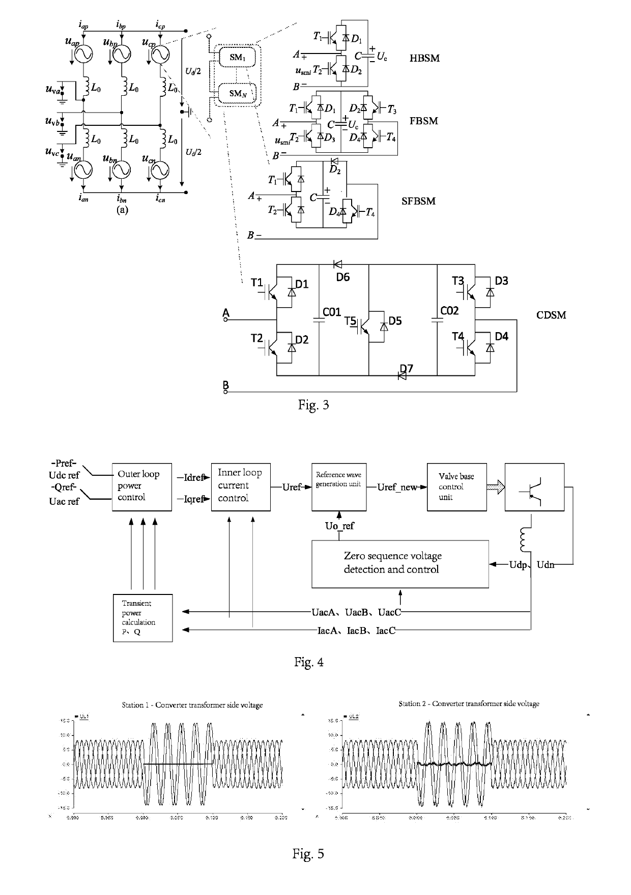
[0060]The present invention provides a method for fault positioning and recovery, which can effectively detect the problems that each station contains a zero sequence voltage of an alternating-current side and cannot easily position a fault caused due to transmission of the zero sequence voltage of the alternating-current side to an opposite-side alternating-current system via a voltage source converter to an opposite-side alternating-current system. By means of the fault recovery method, a non-faulty converter station can get rid of influences of a faulty converter station for rapid recovery, thereby isolating the fault of the faulty station from the alternating system of the non-faulty station. Meanwhile, the provided fault recovery method can further ensure continuous operation during the fault period of the faulty station.

[...


PUM


Abstract

A method for fault positioning and recovery of a voltage source converter includes following steps. Locking a converter station when it is detected that an alternating-current voltage contains a zero sequence voltage or a direct-current voltage contains an unbalanced voltage. Positioning a fault by continuing to detect the zero sequence voltage of an alternating-current side of the converter. Recovering operation of each station after the fault is positioned. The method for fault positioning and recovery is simple, practical, has high reliability, and can effectively detect the problems that each station contains a zero sequence voltage of an alternating-current side and cannot easily position a fault caused due to transmission of the zero sequence voltage of the alternating-current side to an opposite-side alternating-current system via a voltage source converter.

Description

BACKGROUND OF THE INVENTIONTechnical Field[0001]The present invention relates to a field of direct-current power transmission, and in particular, to a method and system for fault positioning and recovery of a voltage source converter.Background Art[0002]A flexible alternating-current and direct-current power transmission technology employs a voltage source converter, which can regulate active power and reactive power separately, hence achieving flexible and convenient control. A receiving-end system can be a passive network, and it is unnecessary to apply an external commutating voltage. An alternating-current side does not need to provide reactive power and a reactive compensation function can be achieved, thereby dynamically compensating reactive power of an alternating-current bus and stabilizing an alternating-current voltage. Therefore, the voltage source converter is one of developing trends of electric power system transmission.[0003]The development of the voltage source conv...

Claims


Application Information

Patent Timeline
IPC IPC(8): H02H7/26H02J3/36
CPCH02H7/262H02J3/36H02H3/063H02H3/06H02H7/26Y02E60/60G01R31/08G01R31/40H02H7/122Y02E40/10Y02E60/00
Inventor LI, GANGLU, YUHU, ZHAOQINGTIAN, JIEDONG, YUNLONGJIANG, TIANGUILI, HAIYINGFENG, YADONGWANG, KELU, JIANGSUI, SHUNKEWANG, HUIWANG, NANNAN
Owner NR ELECTRIC CO LTD
Learn More