
Vertically mounted sulfur adsorbent system

Inactive Publication Date: 2019-05-23
KING FAHD UNIVERSITY OF PETROLEUM AND MINERALS
View PDF0 Cites 0 Cited by
  • Summary
  • Abstract
  • Description
  • Claims
  • Application Information

AI Technical Summary

Benefits of technology

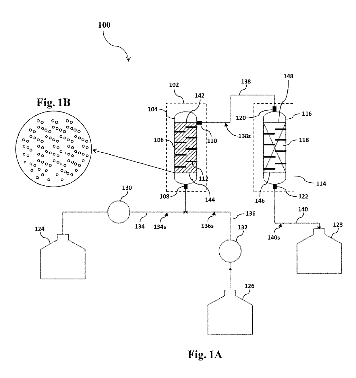
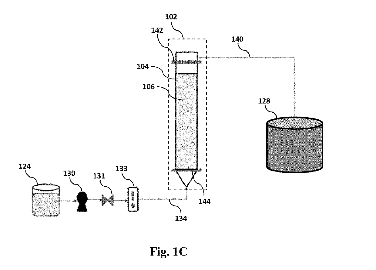
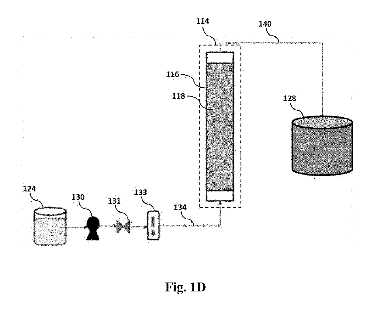
The present patent relates to a sulfur removal system and method for desulfurizing a sulfur-containing hydrocarbon stream. The system includes two reactors, with the first reactor containing a first adsorbent bed and the second reactor containing a second adsorbent bed. The first adsorbent is a cobalt and copper on activated carbon support, while the second adsorbent is also a cobalt and copper on activated carbon support. The first and second adsorbents are designed to remove sulfur compounds from the hydrocarbon stream. The system also includes a liquid reservoir for regenerating the adsorbents and a method for making the adsorbent. The technical effects of the patent include improved sulfur removal efficiency, reduced sulfur concentration in the final product, and improved regenerability of the adsorbents.

Problems solved by technology

This method, however, requires a high temperature, a high pressure, and a large catalyst volume [C. Song, Fuel processing for low-temperature and high-temperature fuel cells: challenges, and opportunities for sustainable development in the 21st century, Catal.

Method used


Image

  • Vertically mounted sulfur adsorbent system
  • Vertically mounted sulfur adsorbent system
  • Vertically mounted sulfur adsorbent system

Examples


example 1

Preparation

[0111]In order to prepare the adsorbent, activated carbon (AC) particles were formed. Accordingly, waste rubber tires were cut into small pieces, and iron wires removed from the rubber pieces. The pieces were cleaned, rinsed with distilled water, and dried at 110° C. for two hours. The granules were then heated to 300° C. to remove all the liquid constituents from the char. Carbonization was performed at around 500° C. in a muffle furnace for five hours, and all adhering organic impurities were oxidized by treating the char with hydrogen peroxide. The char was rinsed thoroughly with distilled water and dried. The carbon black was activated at 900° C. for 5 h, and the resulting activated carbon was rinsed with distilled water and dried. Chemical activation was conducted on the prepared material using 4 M HNO3 (7 g AC / 70 ml) at 90° C. for 3 h in a reflux condenser. Finally, the AC was washed thoroughly with distilled water and dried at 110° C. A detailed protocol for conver...

example 2

on of Standard Solutions

[0114]Six separate standard solutions were prepared by dissolving six sulfuric compounds, including thiophene (T), benzothiophene (BT), dibenzo[b,d]thiophene (DBT), 5-methyl-1-benzothiophene (MBT), 4-methyl dibenzo[b,d]thiophene (MDBT) and 4,6-dimethyldibenzo[b,d]thiophene (DMDBT) into a liquid hydrocarbon to form fuel solutions. A a concentration of the sulfur compounds in the resulting fuel solutions were 50 ppm, 25 ppm, 5 ppm, 1 ppm, and 0.5 ppm.

example 3

e Desulfurization

[0115]A batch mode adsorption was conducted. Accordingly, various amounts, in the range between 0.01 to 0.5 g of adsorbents were introduced into 15 ml of the fuel solution. The T, BT, DBT, MBT, MDBT and DMDBT initial concentrations were 50 ppm. The refractory sulfur compounds solutions containing the adsorbents were mixed well under stirring at room temperature until equilibrium. After adsorption period, samples were collected using a syringe filter (hydrophobic polytetrafluoroethylene) and the concentrations of the sulfur compounds were measured by gas chromatography coupled with sulfur chemiluminescence detector (GC-SCD).


PUM

PropertyMeasurementUnit
volumeaaaaaaaaaa
volumeaaaaaaaaaa
volumeaaaaaaaaaa

Abstract

A sulfur removal system including a first reactor and a second reactor that are located in series to one another each having an adsorbent that includes cobalt and copper on an activated carbon support, a method of desulfurizing a sulfur-containing hydrocarbon stream via the sulfur removal system, and a method of making the adsorbent. Various embodiments of the sulfur removal system, the desulfurizing method, and the method of making the adsorbent is also provided.

Description

STATEMENT OF FUNDING ACKNOWLEDGEMENT[0001]The support provided by King Abdulaziz City for Science and Technology (KACST) through the Science & Technology Unit at King Fand University of Petroleum & Minerals (KFUPM) for funding through a project no. 13-PET393-04 as part of the National Science, Technology and Innovation Plan is acknowledged.BACKGROUND OF THE INVENTIONTechnical Field[0002]The present invention relates to a sulfur removal system with a first and a second reactor and an adsorbent that includes cobalt and copper on an activated carbon support.Description of the Related Art[0003]The “background” description provided herein is for the purpose of generally presenting the context of the disclosure. Work of the presently named inventors, to the extent it is described in this background section, as well as aspects of the description which may not otherwise qualify as prior art at the time of filing, are neither expressly or impliedly admitted as prior art against the present i...

Claims


Application Information

Patent Timeline
Patent Type & Authority Applications(United States)
IPC IPC(8): B01D53/04C10G25/00B01D53/12B01D53/08B01J20/20B01J20/02C10G25/09B01D53/02
CPCB01D53/0423C10G25/003B01D53/12B01D53/08B01J20/20B01J20/0237B01J20/0225C10G25/09B01D53/02B01D2253/25B01D2253/102B01D2253/112B01D2256/24B01D2257/306B01D2259/40083B01D2259/402C10G2300/202
Inventor AWADH, TAWFIK ABDO SALEHAL-HAMMADI, SADDAM AHMED
Owner KING FAHD UNIVERSITY OF PETROLEUM AND MINERALS
Learn More