Reactor using electrical and magnetic fields

a technology of electrical and magnetic fields and reactors, applied in nuclear reactors, climate sustainability, nuclear energy generation, etc., can solve the problems of many obstacles to making it a viable energy source, cost increase, and extraordinary difficulty

Pending Publication Date: 2019-07-04
ALPHA RING INT LTD
View PDF11 Cites 19 Cited by
  • Summary
  • Abstract
  • Description
  • Claims
  • Application Information

AI Technical Summary

Problems solved by technology

The challenge has been to find a way to sustain a fusion reaction in a way that is economical, safe, reliable, and environmentally sound.
This challenge has proved to be extraordinarily difficult.
Even if ICF efforts achieve ignition conditions, there are still many obstacles to making it a viable energy source.
The current estimate for the cost of the project is over $50 billion, and it is likely the costs will continue to rise.
Due to market realities, and the inherent limitations of the tokamak design for fusion power, many analysts doubt that fusion reactors such as ITER will become commercially viable.
Due to the significant change in temperatures at the plasma boundary, there inevitably exists cold neutral species that significantly affect plasma flows.
Rotating plasma devices that do not employ highly ionized plasmas have been considered for fusion research, but the neutrals have always been seen as a problem for reaching fusion conditions.
All credible prior approaches have all faced confinement and engineering issues.
The art's pursuit of the Lawson criterion, or substantially similar paradigms, has led to fusion devices and systems that are large, complex, difficult to manage, expensive, and, as yet, economically unviable.
In particular, a major source of energy loss in conventional fusion systems is radiation due to electron bremsstrahlung and cyclotron motion as mobile electrons interact with ions in the hot plasma.
Because the conventional thinking holds that high temperatures and a strongly-ionized plasma, absent of the presence of a significant presence of neutrals, are required, it was further believed that inexpensive physical containment of the reaction was impossible.
Accordingly, the methods that have been most heavily pursued are directed to complex and expensive schemes to contain the reaction, such as those used in magnetic confinement systems (e.g., the ITER tokamak) and in inertial confinement systems (e.g., NIF laser).
While muon-catalyzed fusion received some attention, efforts to make a muon-catalyzed fusion source have not been successful.
This means that each muon can only catalyze at most a few hundred deuterium-tritium nuclear fusion reactions.
Thus, these two factors—muons being too expensive to make and then sticking too easily to alpha particles—limit muon-catalyzed fusion to a laboratory curiosity.
While the Fleischmann-Pons findings initially received significant press, the reception by the scientific community was largely critical as a group at Georgia Tech University quickly found problems with their neutron detector, and Texas A&M University discovered bad wiring in their thermometers.
First in November of 1989, and again 2004, the DOE concluded that results thus far did not present convincing evidence that useful sources of energy would result from the phenomena attributed to “cold fusion.”
While Indech and others have realized the potential electron screening to lower the Coulombic barrier for fusion reactors, it is doubtful any efforts have been successful.
At most these efforts appear to propose methods for ignition and not a sustained and controlled fusion reaction.
Despite efforts in ICF, magnetic confinement fusion, and various methods of reducing the Coulombic barrier, there is currently no commercially feasible fusion reactor design that exists.

Method used


Image

  • Reactor using electrical and magnetic fields
  • Reactor using electrical and magnetic fields
  • Reactor using electrical and magnetic fields

Examples


first embodiment

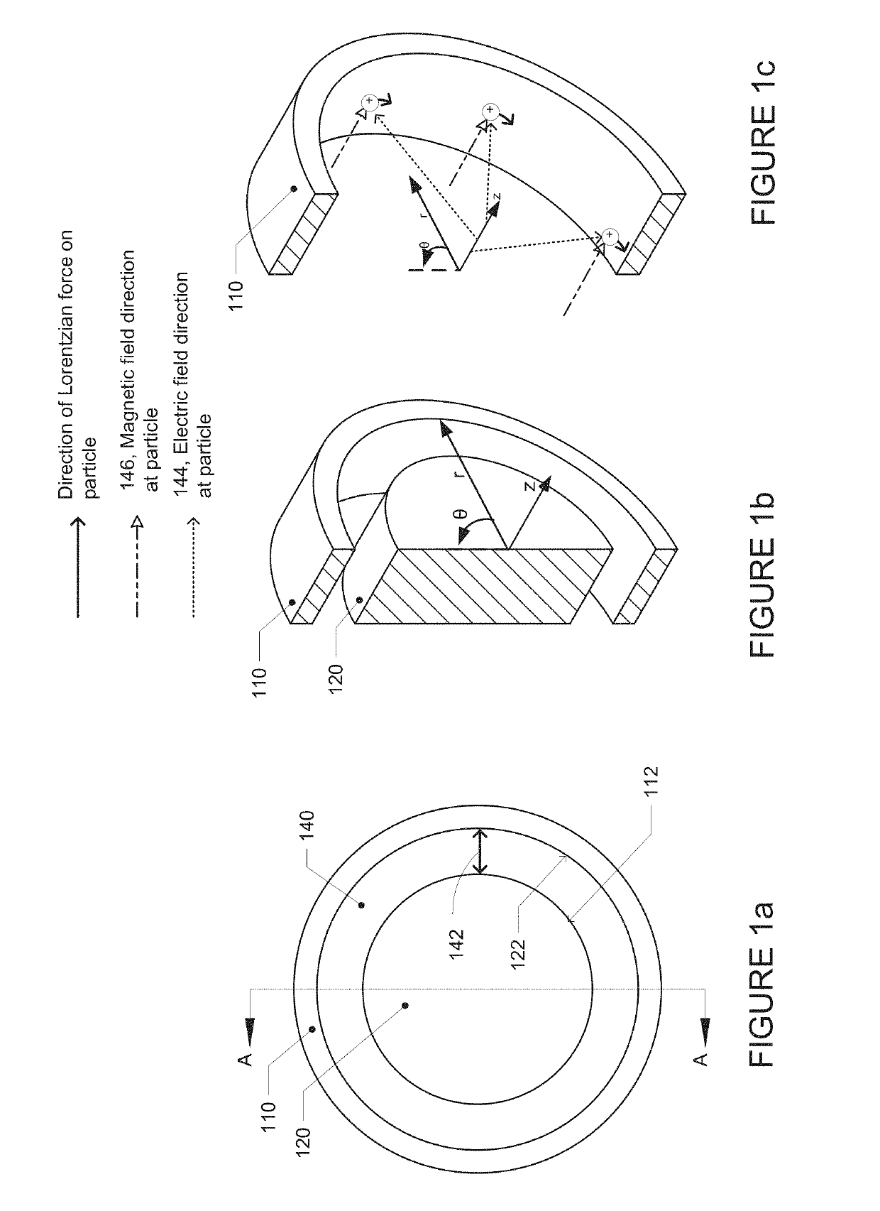
[0159]FIGS. 10a-d depict a first embodiment in which an axial magnetic field is applied by an electromagnet such as a superconducting magnet. FIG. 10a shows an isometric view of a superconducting magnet that surrounds the outer electrode of the reactor. As depicted, the magnet includes an enclosure 1056. FIG. 10b provides the same perspective as FIG. 10a, with the enclosure 1056 of the superconducting magnet removed revealing the superconductive coil windings 1054. FIG. 10c provides a perspective of the reactor as viewed along the z-axis and FIG. 10d is an isometric section view corresponding to the section lines, A-A, shown in FIG. 10c. As shown, the reactor has outer electrode 1010, inner electrode 1020, and a gap 10 that defines the annular space 1040 between the two electrodes. An electrical current (as depicted by arrows in FIG. 10a) passes through superconductive coil windings 1054 that wrap around the reactor, creating an applied magnetic field that is substantially in the z-...

examples

[0244]The following non-limiting examples represent a few embodiments that may be practiced in accordance with the broader principles described herein.

1.) Negative Electrode (Outer Electrode)

[0245]The outer electrode, sometimes called the “shroud” includes a cylindrical metal ring with multiple points of attachment for the lanthanum hexaboride or other target material. The composition of the shroud is typically a refractory metal, such as tantalum (Ta) or tungsten (W), due to the high thermal resistance of refractory metals; however, certain embodiments of the reactor use lower temperature metals such as Alloy 316 Stainless Steel. These embodiments may include a liquid cooling circuit that prevents the shroud from reaching the critical melting temperature of the composition metal. As explained, the outer electrode may be either the more negative or the more positive electrode.

Electrical Conductivity

[0246]The plasma in the reactor is struck between the positive electrode and the nega...


PUM


Abstract

Methods, apparatuses, devices, and systems for producing and controlling and fusion activities of nuclei. Hydrogen atoms or other neutral species (neutrals) are induced to rotational motion in a confinement region as a result of ion-neutral coupling, in which ions are driven by electric and magnetic fields. The controlled fusion activities cover a spectrum of reactions including aneutronic reactions such as proton-boron-11 fusion reactions.

Description

CROSS-REFERENCE TO RELATED APPLICATIONS[0001]This application is a divisional of U.S. patent application Ser. No. 15 / 589,913, filed May 8, 2017, which is a continuation in part of U.S. patent application Ser. No. 14 / 318,246, filed Jun. 27, 2014, which claims the benefit of (i) U.S. provisional application Ser. No. 61 / 840,428 having a filing date of Jun. 27, 2013; (ii) U.S. provisional application Ser. No. 61 / 925,114 filed Jan. 8, 2014; (iii) U.S. provisional application Ser. No. 61 / 925,131 filed Jan. 8, 2014; (iv) U.S. provisional application Ser. No. 61 / 925,122 filed Jan. 8, 2014; (v) U.S. provisional application Ser. No. 61 / 925,148 filed Jan. 8, 2014; (vi) U.S. provisional application Ser. No. 61 / 925,142 filed Jan. 8, 2014; (vii) U.S. provisional application Ser. No. 61 / 841,834 filed Jul. 1, 2013; (viii) U.S. provisional application Ser. No. 61 / 843,015 filed Jul. 4, 2013; U.S. patent application Ser. No. 14 / 318,246 is also a continuation-in-part of U.S. patent application Ser. No....

Claims


Application Information

Patent Timeline
Patent Type & Authority Applications(United States)
IPC IPC(8): G21B1/05G21B3/00
CPCG21B1/05G21B3/006Y02E30/126Y02E30/10
Inventor WONG, ALFRED Y.
Owner ALPHA RING INT LTD
Why Eureka
Try Eureka