Annuloplasty Device and Methods

Active Publication Date: 2019-07-11
DRASLER WILLIAM JOSEPH +1
View PDF0 Cites 27 Cited by
  • Summary
  • Abstract
  • Description
  • Claims
  • Application Information

AI Technical Summary

Benefits of technology

[0048]Yet another method for forming the torus balloon uses a standard cylindrical dilation balloon of 5 mm diameter, for example, that is formed using standard materials and using standard balloon forming methods. The balloon can be cut into segments having a length of one eighth (range of one sixth to one twentieth) of the perimeter of the desired torus balloon perimeter. The cuts can be made at a bevel with respect to the central axial direction of the balloon segment such that the beveled cut of one segment can be located adjacent to and overlapped with the beveled cut of another segment. A mandrel placed within the lumen of the two adjacent segments is used to support the overlap region of the two segments. An outer wrap, such as a shrink wrap is place

Problems solved by technology

Such regurgitant flow can require repair or replacement of the valve.
Such less invasive surgical procedures are not as well developed for replacing abnormally functioning mitral valves.
Often the regurgitant mitral valve is a result of excessive expansion of the left ventricle (LV) leading to abnormal tension and angulation imposed on the mitral valve leaflet.
It is therefore not acceptable to expand a stent indiscriminately outwards as is done in TAVR due to the potential for blockage of the LVOT by the anterior mitral valve leaflet.
The use of barbs or other fixation members to hold the TMVR device securely to the native mitral apparatus can create a set of potential clinical issues that are problematic to the patient.
Furthermore, activation of barbs via a standard dilation balloon can block blood flow through the mitral annulus during balloon inflation causing the patient to temporarily go without oxygen supply to the brain with its ensuing consequences.
Additionally, inflation of a standard balloon can cause the positioning of the stent-valve to become instantaneously displaced and hence inappropriately located across the mitral annulus due to blood pressure and blood flow generated by the LV.
This profile limitation has forced many of the TMVR devices to be delivered via the apex of the heart rather than through a more favorable transvascular and transseptal delivery approach.
The apical approach is not well suited to patients that are older in age or are of higher risk.
Without the stent-valve frame extending into the LV, the native leaflets can overhang into the replacement stent-valve and can interfere with stent-valve function.
What is needed is a stent-valve that does not cause impingement onto the LVO

Method used


Image

  • Annuloplasty Device and Methods
  • Annuloplasty Device and Methods
  • Annuloplasty Device and Methods

Examples


Example

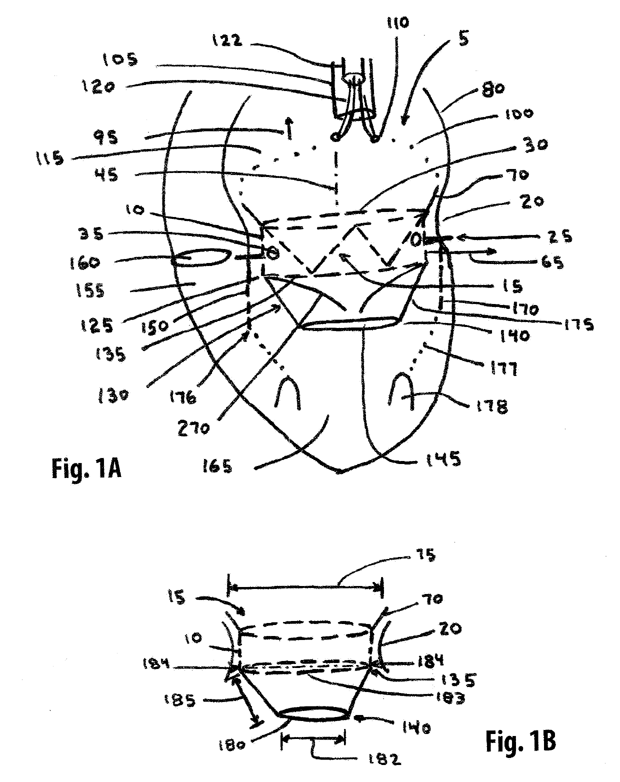
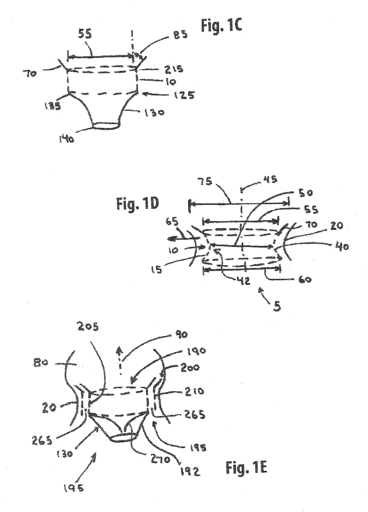
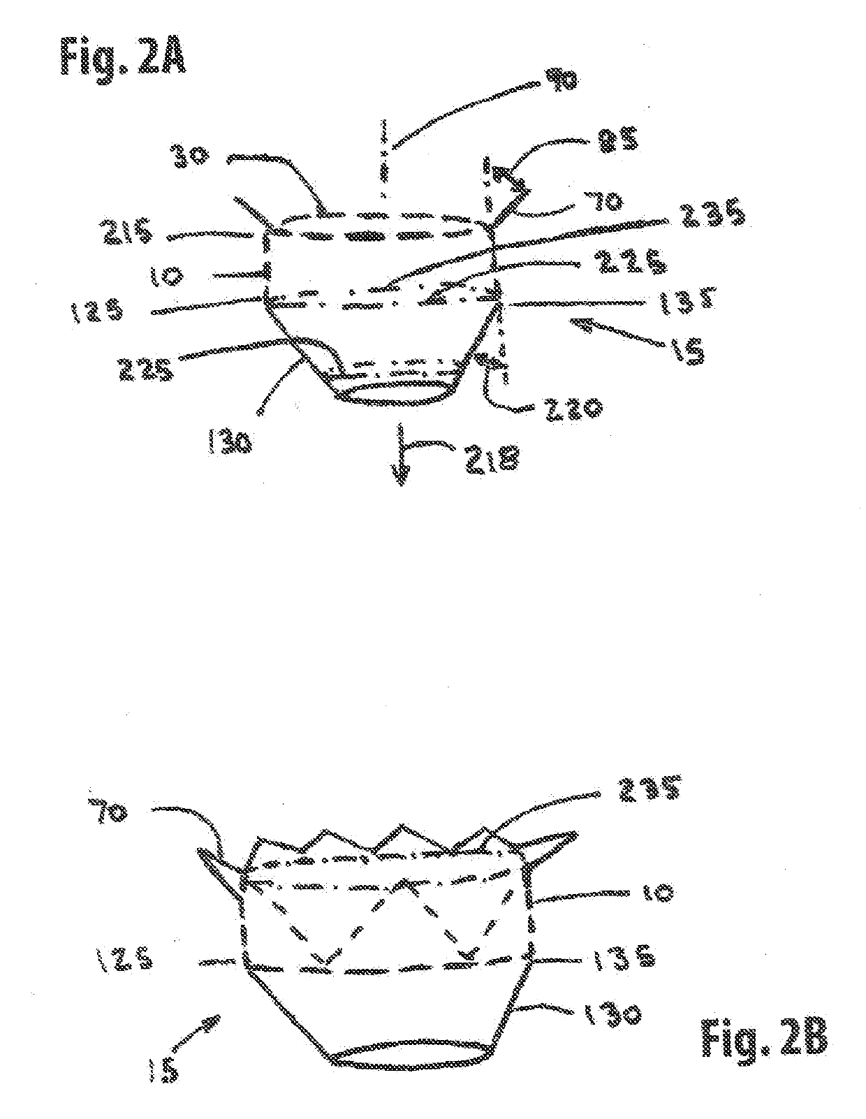
[0221]One embodiment of the present invention comprises a single member stent-valve that is intended as a transcatheter replacement valve for a valve of the heart; the single member stent-valve (5) is intended to be delivered within the lumen of the native heart valve and expanded outwards forming a functioning valve device having replacement leaflets. The valve device will be described in an application for its use as a transcatheter mitral valve replacement (TMVR) although it is understood that the invention can be applied to other valves found within the heart. The invention further comprises a dual member stent valve comprised of two components, a first component or support member and a second component or valve member. The first component is delivered across the annulus of the heart and affixed to the annulus or other native tissues of the heart; the first component does not interfere with function of native valve leaflets such that the mitral valve is fully functional while aw...


PUM


Abstract

An annuloplasty device formed from a Nitinol stent frame that expands into contact with the annulus above the native leaflets. A torus balloon activates barbs along the perimeter to fasten the stent frame to the annulus. A cinch ring is placed under tension to reduce the perimeter of the stent frame. The cinch ring and torus balloon are implanted along with the stent frame.

Description

CROSS REFERENCE TO RELATED APPLICATIONS[0001]This patent application makes reference to and thereby incorporates all information found in the nonprovisional patent application numbered: Ser. No. 15 / 457,626 entitled Two Component Mitral Valve filed 13 Mar. 2017 by William J. Drasler, et. al., and nonprovisional patent application numbered: Ser. No. 16 / 147,823 entitled Straddle Annular Mitral Valve filed on 30 Sep. 2018 by William J. Drasler et. al.; also, this patent application makes reference to and incorporates all information found in provisional patent applications numbered: 62 / 614,451 entitled Retractable Barb Straddle Mitral Valve filed 7 Jan. 2018 by William J. Drasler, and 62 / 618,183 entitled Annuloplasty Device with Torus Balloon filed 17 Jan. 2018 by William J. Drasler.BACKGROUND OF THE INVENTION[0002]Valves of the heart including the aortic valve, mitral valve, and tricuspid valve can become hardened from atherosclerotic plaque and calcium and no longer function normally....

Claims


Application Information

Patent Timeline
IPC IPC(8): A61F2/24
CPCA61F2/2445A61F2/2466A61F2220/0016A61F2230/0065A61F2250/0003A61F2250/0013A61F2/2418A61F2/2433A61F2250/006A61F2/2442A61F2250/001A61F2210/0014A61F2220/0075
Inventor DRASLER, WILLIAM JOSEPHDRASLER, II, WILLIAM JOSEPH
Owner DRASLER WILLIAM JOSEPH
Why Eureka
Try Eureka