
Applicator device

a technology of applicator and thread shaft, which is applied in the field of application devices, can solve the problems of warts or other skin lesions that are not effective or not effective enough, prior art methods that need special care and medical supervision, and prior art applicators may not be durable, so as to reduce the resistance to rotating the thread shaft, the effect of less wear and less wear

Active Publication Date: 2019-08-22
MEDICAL BRANDS RES
View PDF12 Cites 6 Cited by
  • Summary
  • Abstract
  • Description
  • Claims
  • Application Information

AI Technical Summary

Benefits of technology

This patent is about a new way to treat skin lesions, specifically warts, that is safer and more effective than current methods. The treatment involves applying a composition containing vitamin A, which has been found to help prevent the warts from coming back. This method may also promote healing and reduce the risk of reoccurrence.

Problems solved by technology

Many prior art methods to treat warts or other skin lesions are not effective or not effective enough.
Further, some of the prior art methods need specific care and medical supervision, such as the treatment of warts with liquid nitrogen.
Further, many of the prior art applicators comprise materials that deteriorate in time.
Especially, some prior art applicators may not be durable.
Furthermore, many of the prior art applicators do not provide a dosage control of a treatment liquid.

Method used


Image

  • Applicator device
  • Applicator device
  • Applicator device

Examples


Embodiment Construction

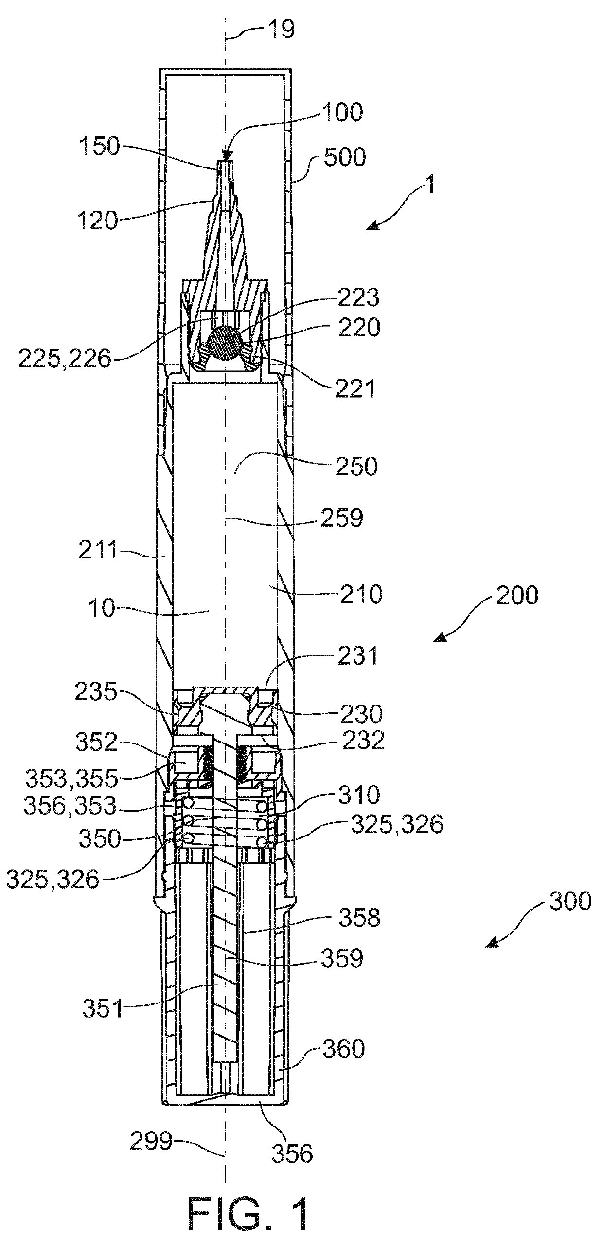
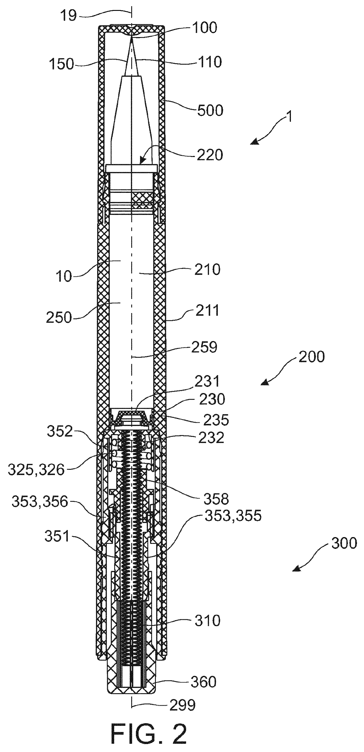
[0121]FIG. 1 schematically depicts an embodiment of the applicator device 1. The embodiment depicted in FIG. 1 is an embodiment wherein the applicator 1 may be actuated by a rotation of the end cap 360. The embodiment depicted in FIG. 2 may be actuated by a translation of the end cap 360. The applicator 1 comprises an applicator tip 100 and a container part 200. Especially, the applicator tip 100 depicts an extreme of the applicator 1 when the closure cap 500 is removed. The figures further depict the device body axis 19.

[0122]The container part 200 comprises a container 210 especially for containing a (treatment) liquid 10 in a storage volume 250. Herein the term “composition” may also be used for the liquid 10. The container part 200 comprises a longitudinal axis 299, or body axis 299. The storage volume 250 is a variable storage volume 250 and is defined by the container wall 211, the valve 220, and the plunger 230. Note: in FIG. 2, only the location of the valve 220 is depicted;...


PUM

PropertyMeasurementUnit
viscosityaaaaaaaaaa
viscosityaaaaaaaaaa
viscosityaaaaaaaaaa

Abstract

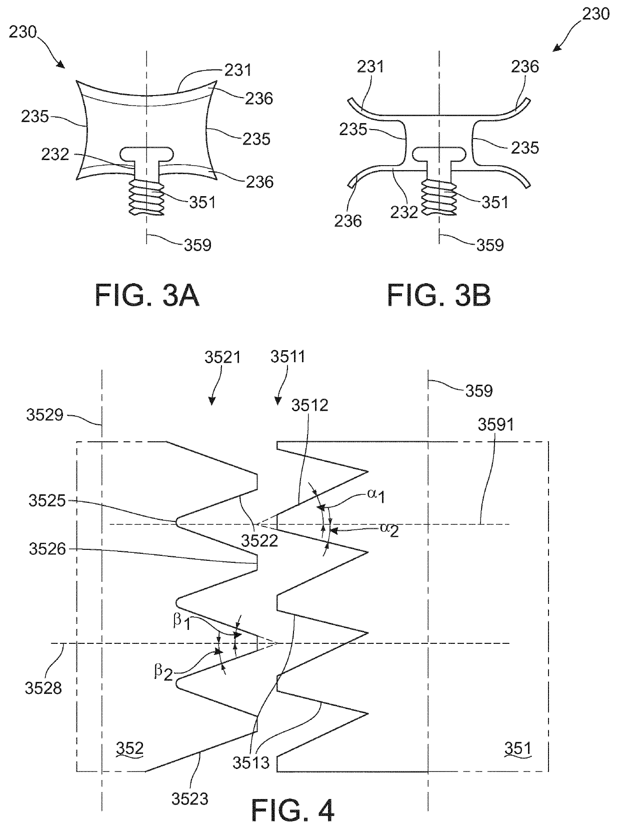
The invention relates to an applicator device comprising an applicator tip and a container part, wherein the container part comprises: (i) a container comprising a container wall, a valve, and a plunger, wherein the container wall, the valve, and the plunger together define a storage volume for containing a liquid, wherein the plunger comprises a circumferential wall, sealingly contacting the container wall; and (ii) a plunger advance system functionally coupled to the plunger and configured to advance the plunger for reducing the storage volume for expelling at least part of the liquid via said valve to said tip, wherein the plunger advance system is arranged outside the storage volume; wherein (a) the valve comprises a first spring system comprising a first spring material comprising a stainless steel material comprising a molybdenum content selected in the range of 0.5-7 wt. %, and (b) the plunger advance system comprises a second spring system comprising a second spring material comprising a stainless steel material comprising a molybdenum content selected in the range of 0.5-7 wt. %, applies; and the plunger advance system comprises a polymer selected from the group consisting of polypropylene (PP), ethylene chlorotrifluoroethylene (ECTFE), and polyoxymethylene (POM); and wherein the plunger advance system comprises a spindle system comprising a ratchet system comprising a first element and a second element, wherein the second spring system is configured to provide the first element and the second element to engage on each other.

Description

FIELD OF THE INVENTION[0001]The invention relates to an applicator device and its use.BACKGROUND OF THE INVENTION[0002]Various compositions are known for the treatment of skin lesions, such as warts, corns and calluses, actinic keratosis, keratosis pilaris, acne, tattoo removal / correction, skin hyperpigmentation and / or nail lesions, such as ingrown toenails and / or lesions in mucous membranes, such as cold sores and mouth ulcers. WO2012007584, for instance, describes a composition for the treatment of superficial lesions, in particular skin lesions, mucous membrane lesions and / or nail lesions, an applicator comprising such a composition and the use of such a composition. The composition comprises an effective amount of trichloroacetic acid, at least one thickener, and at a physiologically acceptable solvent. The composition is considered effective against a plethora of superficial lesions selected from the group consisting of viral warts, verrucae, water warts (molluscum contagiosum)...

Claims


Application Information

Patent Timeline
Patent Type & Authority Applications(United States)
IPC IPC(8): A61M35/00A61K8/36A61K8/81
CPCA61M35/003A61K8/36A61K8/8147B65D83/0005A45D34/042A45D2200/055
Inventor HENDRIKS, MAIKELBOUTER, PIETERNELLA ANNA MARIA
Owner MEDICAL BRANDS RES
Learn More