Bidirectional DC DC Converter for Renewable Energy Storage

a technology of renewable energy storage and dc converter, which is applied in the direction of electric variable regulation, process and machine control, instruments, etc., to achieve the effect of reducing effort and disruption

Inactive Publication Date: 2019-09-12
KRZYWINSKI EUGENE F +2
View PDF4 Cites 2 Cited by
  • Summary
  • Abstract
  • Description
  • Claims
  • Application Information

AI Technical Summary

Benefits of technology

[0008]The invention provides an electrical adapter between renewable energy sources and loads such that energy storage elements can be added to the system with minimal effort and disruption. In one embodiment, the invention is inserted into an existing solar energy system that consists of a photovoltaic array connected to a grid tied inverter and where it is desired to add an energy storage element to said system. Such energy storage systems have a duality in that they are both loads (charging) and sources (discharging) and must match the system's electrical characteristics in order to function properly. Typically, such existing systems have high DC voltage magnitudes that are incompatible with low DC voltage magnitude energy storage elements and therefore a voltage converter is required to adapt the storage element to the array. Photovoltaic arrays need maximum power point tracking (MPPT) elements to ensure maximum power harvesting from the array and this function is typically provided by the load, in most cases a grid tied inverter. During the charge phase of the energy storage system, the existing load which typically provides the MPPT function remains operational as designed and the invention routes a configurable amount of the power to the battery to be charged. During the discharge phase, the converter must match the input characteristics of the load so that to the load it simply appears as a PV source, thereby allowing optimum blending of battery energy and maximum power PV energy to be presented to the load.
[0009]The invention combines the MPPT-following function, the voltage conversion function, the intelligent transfer function, with intelligent electronics for control of operation, either preprogrammed or user adjustable. In an embodiment, the invention also provides the charge control function for energy storage systems such as batteries and can interface to the battery's management system for optimal control and operation. In an embodiment, detailed operational data is collected by the invention and transmitted to a collection system that provides such data to the system owner or operator. In another embodiment, additional energy can be provided through the apparatus from an AC power source such as the utility grid, microgrids or AC generating equipment. In another embodiment, a secondary off-grid inverter can be connected to the system providing power to dedicated, critical loads when the primary, grid tied inverter is off-line.

Problems solved by technology

Typically, such existing systems have high DC voltage magnitudes that are incompatible with low DC voltage magnitude energy storage elements and therefore a voltage converter is required to adapt the storage element to the array.

Method used


Image

  • Bidirectional DC DC Converter for Renewable Energy Storage
  • Bidirectional DC DC Converter for Renewable Energy Storage
  • Bidirectional DC DC Converter for Renewable Energy Storage

Examples


Embodiment Construction

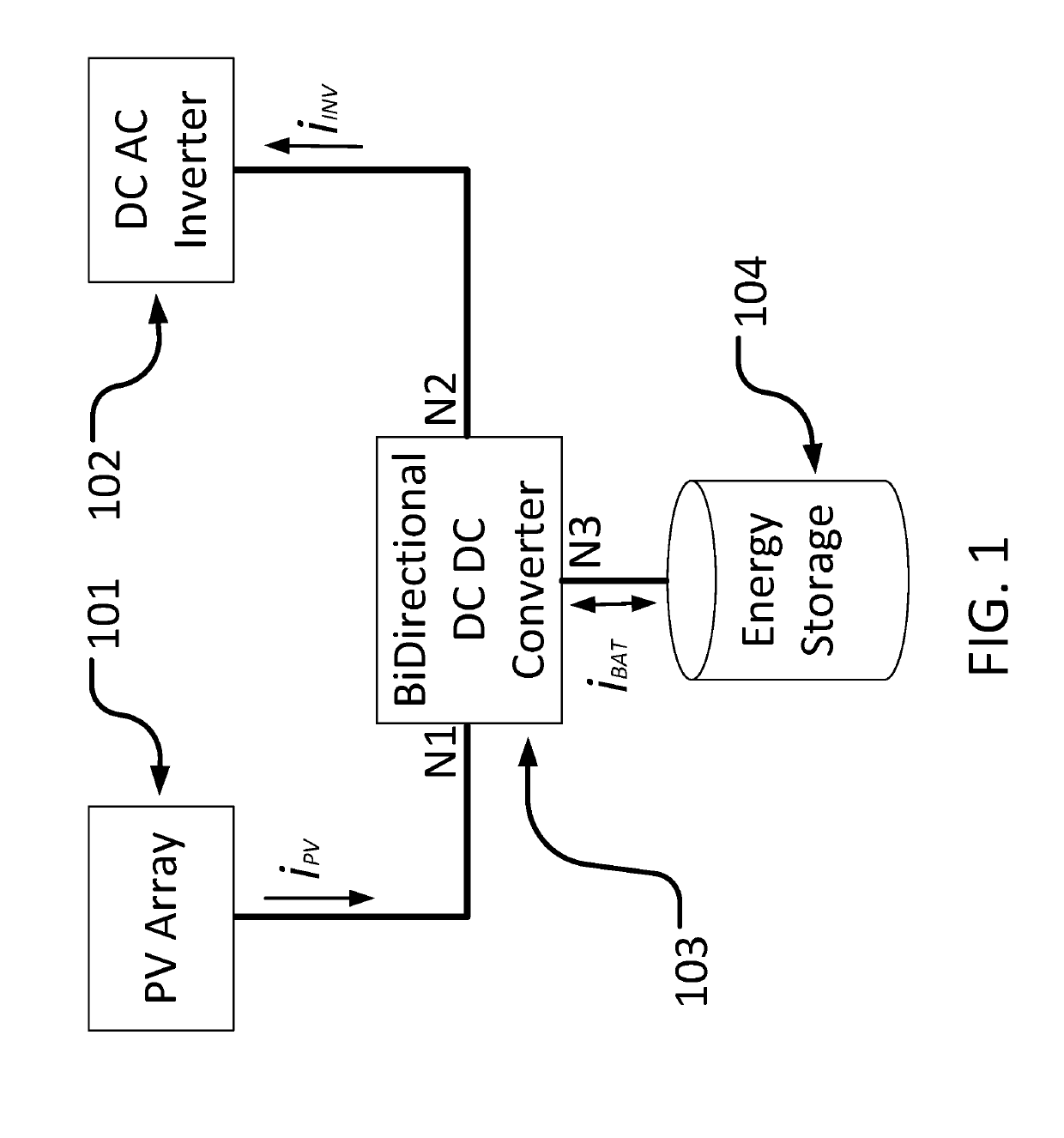
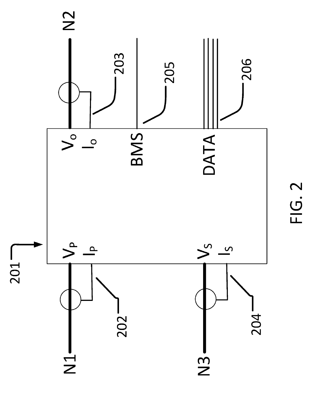
[0017]FIG. 1 shows an embodiment of the invention and where it is positioned between the energy source [101] PV array and the grid tied inverter [102]. The PV array [101] outputs power as the product of voltage and current and connects to N1 [202] of the DC DC Converter [103]. The controller [FIG. 2] measures the current and voltage at N1 [202] and the controller's algorithm determines the power flow and ratios between attached storage [104] and the grid tied inverter [102]. The controller [FIG. 2] also monitors the voltage and current at node 2, N2 [203] to determine the operating parameters of the DC DC converter. The controller [FIG. 2] also receives information from external sources such as the battery BMS [205] and business rules from the user via data lines [206] to determine if correct ratios are being applied to both the power flow and energy storage. By measuring the node currents and node voltages, the controller [FIG. 2] will determine the PV system maximum power point fo...


PUM


Abstract

This disclosure describes a unique bidirectional DC DC converter that transfers power between a high voltage source, such as the DC voltage in a solar PV array, a low voltage energy storage element such as a battery pack, and an inverter that is controlling the operating voltage of the solar PV array. Its novelty is that it is transparent to the inverter's control mechanism and is perceived as a source equivalent to the existing solar PV. By controlling the charge and discharge times of the energy storage element, the solar power that is harvested during the sun hour day can be metered back to the inverter at more optimal times, either for self consumption or to take advantage of higher rates of power sold to a connected utility. The bidirectional DC DC converter is unique in its operation in that it utilizes synchronous rectification when down-converting higher voltages to lower voltages and in that it uses high speed Silicon Carbide, or Gallium Nitride devices necessary for such rectification. Another unique aspect is the variable overlapping of the drive signal of the switches in the boost (second) stage of the converter which allows for a continuous range of voltage levels of the transferred power from energy storage element to the primary stage and output.

Description

CROSS REFERENCE TO RELATED APPLICATIONS[0001]This application claims the benefit of U.S. Provisional Application No. 62 / 641,197 “DC DC Converter with MPPT and Transfer Switch” filed on Mar. 9, 2018, the entirety of which is incorporated herein by this reference thereto.TECHNICAL FIELD OF THE INVENTION[0002]The invention relates to bidirectional DC DC converters between sources, loads and energy storage devices.BACKGROUND[0003]Solar power in the US is primarily grid tied to avail the owner of net metering provisions offered by the local utility. In many instances, net metering provisions are under going change which decreases the net metering credit to the owner by changing the on-peak hours, when net metering credits are of highest value, to later times when power feed from the owner to the grid is more valuable to the utility. The power to be fed back is dependent on the sun's profile, not time, and so maximum solar energy harvest is now out of sync with utility demand. To accommod...

Claims


Application Information

Patent Timeline
Patent Type & Authority Applications(United States)
IPC IPC(8): H02M3/335H02J3/38H02J3/32
CPCH02M3/33592H02M3/33584H02J3/385H02J3/32H02J7/35H02J2300/26H02J3/381Y02B70/10Y02E10/56H02J3/46H02J3/40
Inventor KRZYWINSKI, EUGENE F.REED, WILLIAM B.ALLEN, JR., JAMES A.
Owner KRZYWINSKI EUGENE F
Why Eureka
Try Eureka