Passive, gravity-driven system for treatment of an effluent in a diagnostic system

Active Publication Date: 2019-10-03
VENTANA MEDICAL SYST INC
0 Cites 0 Cited by

AI-Extracted Technical Summary

Problems solved by technology

However, DAB is a chemical with potential mutagenic and carcinogenic activity, and it increases the toxicity of waste streams from slide stainers used in IHC systems, which demands hazardous waste disposal.
However, Rhett does not teach any method of treating the wastes after collection.
However, Bogen does not feature any method of tr...

Benefits of technology

[0012]In other embodiments, the system comprises a radical generator coupled to a radical generating reservoir. The effluent may be routed from the homogenizing reservoir to the radical generating reservoir via a channel, with gravity facilitating flow of the effluent. Once in the radical generating reservoir, the effluent is exposed to the radical generator. The radical initiator in the effluent activates AOPs that breakdown ...

Abstract

Automated systems to make target compounds from slide stainer waste streams inactive utilizing advanced oxidation processes are described herein. Advanced oxidation processes are promoted by UV irradiation and further accelerated by use of radical initiators, such as hydrogen peroxide. The automated systems further include mechanisms for segregating components of the waste streams.

Application Domain

Water/sewage treatment by irradiationWater treatment compounds +3

Technology Topic

ChemistryDiagnostic system +8

Image

  • Passive, gravity-driven system for treatment of an effluent in a diagnostic system
  • Passive, gravity-driven system for treatment of an effluent in a diagnostic system
  • Passive, gravity-driven system for treatment of an effluent in a diagnostic system

Examples

  • Experimental program(16)

Example

Embodiment 1
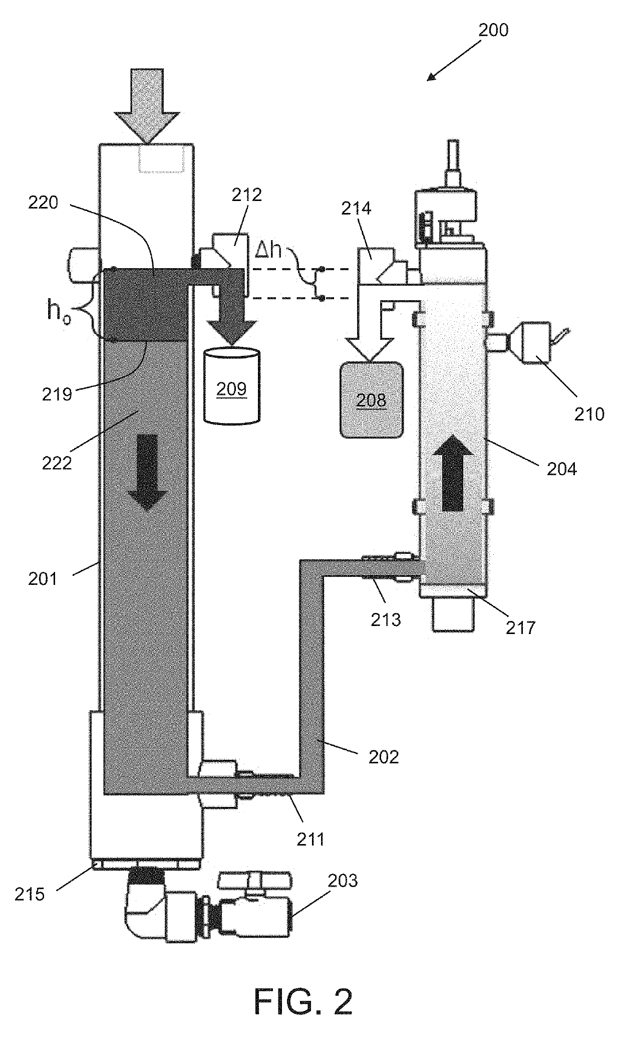
[0126]Liquid cover slip (LCS) has a specific gravity of 0.8. For a Δh=0.5 inches, then h0, which is the height of the oil layer, is calculated using the formula,
Δ h = h 0 [ 1 - ρ 0 ρ w ] ,
to be h0=2.5 inches, or 63.5 mm.

Example

Embodiment 2
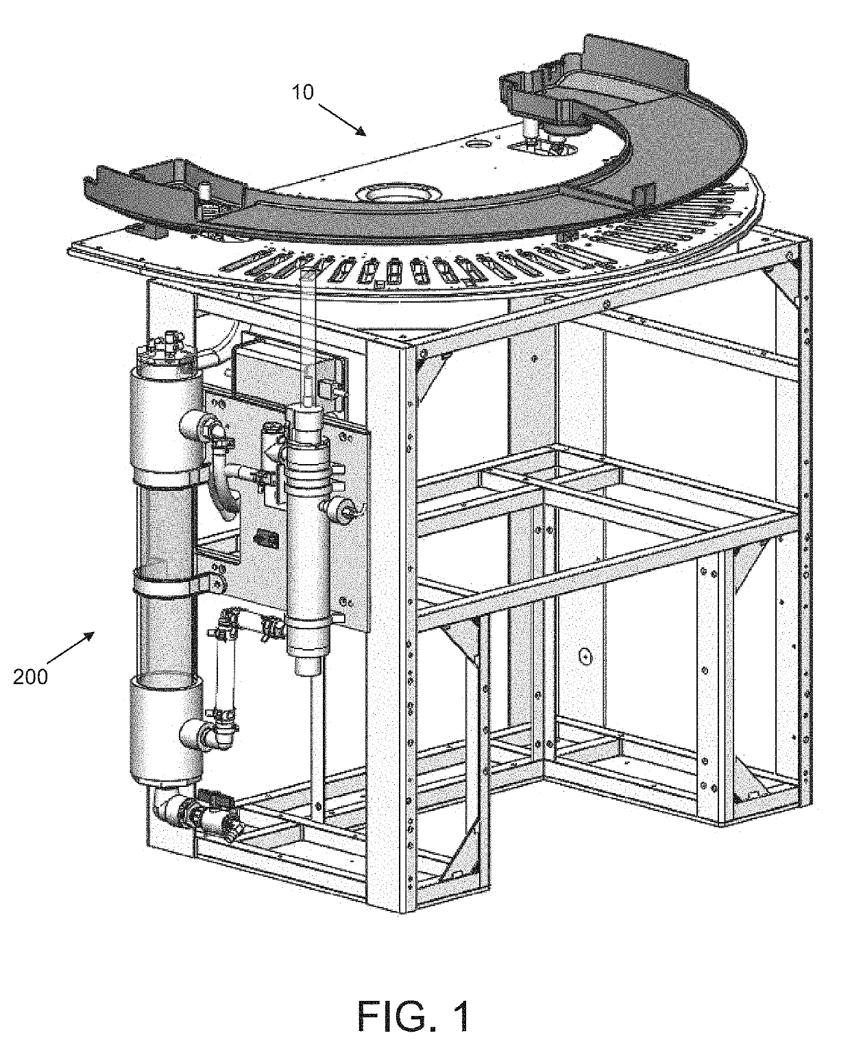
[0127]Referring to FIG. 2, the homogenizing reservoir (201) may be a cylindrical column having a 4,400 mm2 internal, cross-sectional surface area and height ranging from about 600 mm to 1000 mm. The radical generating reservoir (204) may be a cylindrical column having a tubular UV bulb co-axially disposed therein. Excluding the cross-sectional surface area of the tubular UV bulb, the remaining internal, cross-sectional surface area of the radical generating reservoir (204) is about 2,330 mm2. A height of the radical generating reservoir (204) is at least 300 mm, of which 270 mm is the travel length. Given a Δh=0.5 inches, then h0 of the oil layer is about 63.5 mm. The channel (202) has a cross-sectional surface area of about 283 mm2 and a capacity of about 0.15 L.
[0128]The waste stream enters the cylindrical column at an average flow rate of about 50 ml/min. A height of the aqueous layer is about 500 mm and the downward velocity of the aqueous layer is about 10 mm/min. Thus, the travel time of the aqueous layer down the column is about 50 minutes, which provides a sufficient residence time to ensure that the aqueous fluid components are evenly mixed, at least at the fluid outlet of the column, to form the target effluent. The target effluent flows through the channel (202) in about 1.5 minutes. The target effluent then flows through the radical generating reservoir (204) at an upward velocity of about 21 mm/min, thus the travel time of the target effluent through the radical generating reservoir (204) for irradiation is about 12.8 minutes. The combined fluid volume in the column, channel, and radical generating reservoir (204) is about 3 L.

Example

Embodiment 3
[0129]Given the same system and dimensions as in Embodiment 2, the waste stream enters the cylindrical column at an average flow rate of about 23 ml/min. A height of the aqueous layer is about 500 mm and the downward velocity of the aqueous layer is about 5 mm/min. Thus, the travel time of the aqueous layer down the column is about 100 minutes, which provides a sufficient residence time to ensure that the aqueous fluid components are evenly mixed, at least at the fluid outlet of the column, to form the target effluent. The target effluent flows through the channel (202) in about 3 minutes. The target effluent then flows through the radical generating reservoir (204) at an upward velocity of about 10 mm/min, thus the travel time of the target effluent through the radical generating reservoir (204) for irradiation is about 27 minutes. The combined fluid volume in the column, channel, and radical generating reservoir (204) is about 3 L.
[0130]The present invention is not limited to the aforementioned system dimensions, fluid velocities, and residence times. In some embodiments, said dimensions may be tailored to a specific automated system.
Experimental
[0131]Investigations were performed to examine various levers that could impact AOP activity in BenchMark ISH/ISH automated instrument waste to destroy DAB. These levers were tested in DDI water, Reaction Buffer and in BenchMark DAB IHC waste matrices. These levers were tested in a flow-through UV light source test bed device (i.e. in-line UV water sterilizers), a top-down non-contact irradiation source (tRED test bed), and a tRED test bed which combined water/oil separation and DAB aqueous waste UV irradiation.
[0132]Oil Separation Principles
[0133]Experimental data was obtained using BenchMark Ultra instrument as the slide stainer. Typical liquid cover slip (LCS) to aqueous ratios on the BenchMark Ultra instrument are approximately 20/80%, with the LCS (oil) being used for the high temperature steps typically to mitigate evaporative losses. Due to random access processing, LCS can be present at any time in the combined waste stream. Two separation principles are invoked for separation of LCS from aqueous waste: buoyancy (FIG. 2) and optional filtration/coalescence (FIG. 26B). Both are based on gravity driven flow only and do not require any pumping.
[0134]The primary separation principle is based on buoyancy in a standing tube/chamber. Typical LCS (Oil) density is 0.79-0.81 g/cm3 and therefore LCS floats to the top of the surface of the aqueous layer over time, particularly in low flow scenarios. For buoyancy separation to work properly, a fully charged system is required. Typically, this would be accomplished by filling the whole system with aqueous fluid up to a level line. In case of a partially filled system, LCS discharged from the drip-pan could be funneled into the aqueous path and partially coat the UVC lamp, which forms a degrading layer over time. Thus, a height adjustment may be necessary between the oil separation layer and aqueous separation layer. This adjustment is needed to allow proper layer separation between LCS and aqueous to occur in the homogenizing chamber and to account for differences in density (LCS≈0.8 vs. aqueous≈1).
[0135]The secondary separation principle is based on a hydrophilic filter, such as a nylon wound filter with 5/10/15 micron pore size, Universal Filter Italiana, product number (“p/n”) UN5R5P, UN10R5P, UN15R5P) rejecting oil (e.g. LCS) while letting aqueous media pass through. The hydrophilic filter works as a coalescing media, allowing smaller oil droplets to be absorbed by the fibers of the filter and aggregate into larger droplets. Open media porosity (5 microns) and hydrophilicity allows for water to pass through the filter (radially from outside to inside) and for oil to remain in the radial fluid sleeve outside of the filter.
[0136]Due to the hydrophilic/coalescing filter being constructed of wound nylon, the surface area of the filter (˜100 cm2) is rather large, and due to low flow rates (˜50 ml/min) and the multi-layered porosity of the filter media, fouling of the surface by exposure to oil is reduced (demonstrated by 4+ months of equivalent use of same filter media, being exposed to mixtures of LCS and aqueous).
[0137]High Performance Liquid Chromatography (“HPLC”) Analytical Methods
[0138]DAB degradation rates were determined using HPLC analysis to monitor DAB concentration change in Milli-Q® deionized (“DDI”) water, BenchMark Reaction Buffer and BenchMark IHC waste matrices. HPLC analyses were performed on a Waters Acquity Ultra Performance Liquid Chromatography (“UPLC”) instrument with photodiode array (“PDA”) detection. Standard reverse phase chromatography was used for UPLC analyses in BenchMark Reaction Buffer and DDI water matrices. Reverse phase HPLC chromatography with ion-pairing was used for DAB analysis in BenchMark waste. DAB samples were analyzed without filtration or dilution.
[0139]A. Reverse Phase UPLC Analytical Method
[0140]A Waters ACQUITY UPLC Bridged Ethylene Hybrid (“BEH”) C18 Column 1×50 mm (1.7μ) UPLC column was used. The eluents were A: 0.1% formic acid in liquid chromatography mass spectrometry (“LCMS”) water, and B: 0.1% formic acid in acetonitrile. The flow rate was 0.2 mL/min, the column temperature was 40° C., and the injection volume was 8 L. PDA detection wavelengths were 210 to 499 nm (2.4 nm resolution and 20 points/sec). The expected retention time of DAB and 2-Hydroxypyridine (2-HOPyr) was 0.35 min and 0.54 min, respectively. Representative HPLC spectra (274 nm are shown in FIGS. 11A-11C. The gradient profile is shown in Table 1.
TABLE 1 Gradient Profile Time (min) % A % B 0 99 1 1 99 1 6 20 80 7 20 80 8 99 1 10 99 1
[0141]B. Reverse Phase HPLC with Ion-Pairing
[0142]A SIELC PrimeSep S column 2.1×100 mm (5μ) and 2.1×10 mm guard column HPLC column was used. The eluents were 40% acetonitrile in 50 mM ammonium formate (pH=4.0). The flow rate was 0.2 mL/min, the gradient profile was an isocratic elution, the column temperature was 30° C., and the injection volume was 8 μL. The PDA detection wavelengths were 210 to 499 nm (2.4 nm resolution and 20 pts/sec). The expected retention time (in BenchMark waste) for DAB and 2-HOPyr was 2.56 min and 1.64 min, respectively. Representative HPLC spectra (310 nm) are displayed in FIGS. 12A-12C.
[0143]UV Irradiated Test Beds
[0144]A. Flow-Through UV Irradiation Test Beds
[0145]Multiple UV irradiation flow-through systems were used to examine UV promoted DAB oxidation. A commercial in-line UV water sterilizers with preset lamp wattage and UV irradiation chamber geometry, namely, an Aquatop 10 W In-line UV sterilizer (Aquatop p/n: IL10-UV), was used to treat water up to a 211 gallon/hour flow rate. The sterilizer featured an external variable-speed micropump gear pump that controlled fluid flow rates with the assistance of an independent power supply. Samples were irradiated with active mixing, dwell mixing, or no mixing. For in-line UV sterilizers that were used without mixing pumps, inversion mixing was performed to create a uniform sample prior to sampling. Multiple UV sterilizer UV lamp wattages were examined (10, 18 and 55 W). Multiple UV irradiation sources may be installed adjacently with serial connection to each other to increase effluent exposure time.
[0146]B. Top-Down UV Irradiation Test Beds
[0147]As shown in FIGS. 9A-9C, a test bed was prepared to investigate top-down UV irradiation systems without direct liquid contact to the UV irradiation source (also referred to as “UV lamp light”). This test bed used two 18 W lamps to irradiate the fluid matrix from above while the liquid meandered through a predetermined path in the metal tray below to control sample exposure time. The UV light sources may be installed adjacently in parallel connection to each other (e.g. UV light array, etc.) to increase the power of the array. Alternatively, the UV light sources may be installed serially to increase exposure time. A second bottom irradiation plastic container was prepared without the pathway. UV light is absorbed as it goes through a liquid medium causing the aqueous layer furthest from the lamp to receive less UV irradiation. This test bed was used to examine liquid layer thickness and waste matrix impurities (i.e. LCS, DAB oxidation products, etc.) impact on DAB UV decomposition rates.
[0148]C. UV Lamp Characterization
[0149]A mercury lamp was used as a primary UV light source for its lower cost and discrete emission wavelengths. Lamps with more continuous emission spectra include xenon arc, deuterium arc, mercury-xenon arc, metal-halide arc and tungsten halogen incandescent lamps. Other UV light sources are available and could provide similar impact such as UV LEDs, UV lasers, etc. The Aquatop 10 W UV lamp source for the in-line UV sterilizer was characterized by reading its emission spectrum by a fluorescence detector. The lamp was wrapped in tin foil that contained a small hole for light emission to the fluorescence detector. A list of relevant UV light wavelengths and their photon energies can be found below in Table 2. UVC light at 253 nm can perform most of the DAB oxidation since it provides higher energy.
TABLE 2 Relevant UV Light Wavelengths and Their Photon Energy. Wavelength UV Light Name Abbreviation (nm) Photon energy (eV, aJ) Ultraviolet A UVA 315-400 3.10-3.94, 0.497-0.631 Ultraviolet B UVB 280-315 3.94-4.43, 0.631-0.710 Ultraviolet C UVC 100-280 4.43-12.4, 0.710-1.987
[0150]DAB UV Oxidation Experimental Results
[0151]A. Sample Mixing Impact
[0152]Initial DAB UV oxidation experiments were performed in the Aquatop 10 W in-line UV sterilizer (Aquatop p/n: IL10-UV) with variable mechanical mixing using the Micropump unit. A DAB sample in DDI water (68.1 mg/L) was treated with 3% hydrogen peroxide as a radical initiator (1 mL per approx. 225 mL DAB sample). The sample was irradiated by UV light (10 min) either with constant mixing or with quick dwell mixing to create a uniform sample prior to sampling. The reaction mixture was analyzed by UPLC every 2 minutes through 10 minutes. As shown in FIG. 13A, the DAB oxidation rates were accelerated through mechanical mixing. Mixing aided the diffusion of the homolytic hydrogen peroxide UV oxidation product (HO.), which oxidized DAB.
[0153]DAB oxidation continued in DDI water during storage at 10° C. on the UPLC. The DAB monomer was not detected by UPLC analysis in samples after storage overnight even if they only received 2 minutes UV irradiation. Moreover, the AOPs generated by UV light and hydrogen peroxide effectively polymerized DAB from DDI water when the sample was actively mixed during UV irradiation (FIGS. 13B-13C). The active mechanical mixing increased the intermolecular polymerization of the oxidized DAB causing it to form larger polymers, which readily precipitated from solution. The precipitated DAB polymers were not observed for mixed samples on the first day. No precipitation was observed in dwell mixed samples after storage overnight. Complete DAB precipitation would be advantageous, as it would promote conditions where all DAB byproducts could be filtered from the matrix.
[0154]DAB UV oxidation rates slowed even further when DAB samples were irradiated in DDI water without any mixing. Approximately 34% of the DAB monomer was detected after 15 minutes of static UV irradiation. This was about the same DAB monomer concentration observed at 10 minutes UV irradiation with dwell mixing. Mechanical dwell mixing was eventually replaced by simple inversion of the in-line UV sterilizer twice to homogenize the liquid prior to sampling. Similar results DAB UV oxidation rates were observed. Data is not shown. Aeration was not well tolerated in BenchMark IHC waste matrices. The BenchMark IHC waste surfactants caused the DAB sample to bubble/foam when aerated complicating DAB degradation.
[0155]B. Hydrogen Peroxide Impact
[0156]DAB UV oxidation experiments were performed in the Aquatop 10 W in-line UV sterilizer as above with variable hydrogen peroxide radical initiator concentrations. A DAB sample in DDI water (68.1 mg/L) was irradiated with or without the presence of 3% hydrogen peroxide (1 mL per approx. 225 mL DAB sample). The sample was irradiated by UV light (60 to 90 min). The Aquatop in-line sterilizer was inverted (2×) using an air pocket to mix the matrix uniformly prior to sampling. The reaction mixture was analyzed by UPLC every 10 minutes.
[0157]The UV irradiation effectively promoted DAB oxidation in absence of hydrogen peroxide radical initiator; however, the DAB oxidation rate was accelerated by the additional hydrogen peroxide (FIG. 14A). The DAB UV oxidation reaction approached the HPLC analysis LOD sooner. No DAB monomer was detected after 50 minutes of UV irradiation in the presence of hydrogen peroxide. Approximately 10% of the DAB monomer was still detectable after 60 minutes UV irradiation in absence of hydrogen peroxide. The DAB decomposition still continued in DDI water during storage at 10° C. on the UPLC even in the absence of hydrogen peroxide. No DAB monomer was detected by UPLC analysis in samples that were stored overnight even after only 2 minutes of UV irradiation independent of hydrogen peroxide radical initiator. The AOPs generated by UV light and hydrogen peroxide effectively polymerized DAB from DDI water when the sample treated with UV irradiation for 30 minutes or longer (FIGS. 14B-14C). This time was significantly longer than the 6 minute period that occurred with active mixing (FIGS. 13B-13C). No DAB polymer precipitates were observed after storage overnight in absence of hydrogen peroxide.
[0158]C. DAB Sample Matrix Impact
[0159]DAB UV oxidation experiments were performed in the Aquatop 10 W in-line UV sterilizer as above with variable sample matrices (i.e. DDI water versus BenchMark IHC Waste). A DAB sample in the matrix (68.1 mg/L DAB in DDI water and 136.2 mg/L in BenchMark IHC Waste) was irradiated without the presence of 3% hydrogen peroxide. A fresh BenchMark Ultra OptiView DAB with TSA Amp IHC Waste was used for this experiment where the aqueous layer was separated from a majority of the LCS by gravity. The BenchMark IHC Waste still contained some LCS, which was finely dispersed with the BenchMark IHC waste surfactants. Both samples were irradiated by UV light for 75 minutes. The Aquatop in-line sterilizer was inverted (2×) using an air pocket to mix the matrix uniformly prior to sampling. The reaction mixture was analyzed by UPLC every 10 minutes.
[0160]UV irradiation effectively induced DAB oxidation both matrices; however, the DAB oxidation rate was slower in BenchMark IHC Waste (FIG. 15). Approximately 10% of the DAB monomer was still detectable after 60 minutes UV irradiation in DDI water while about 21% DAB monomer was still detectable 60 minutes UV irradiation in BenchMark waste. The DAB UV oxidation rate in water was slower in BenchMark waste presumably because the waste matrix absorbed more UV light than DDI water.
[0161]A DAB sample in BenchMark Ultra OptiView DAB with TSA Amp IHC Waste (136.2 mg/L) was irradiated with or without the presence of 3% hydrogen peroxide. The DAB UV oxidation rate in BenchMark IHC waste was slower than in water so the hydrogen peroxide concentration was increased to 3 mL peroxide per 250 mL of the DAB sample in BenchMark waste. The UV irradiation effectively induced DAB oxidation in BenchMark waste with the increase hydrogen peroxide concentration (FIG. 16). The DAB monomer was at or below the HPLC LOD in waste within 30 minutes.
[0162]The DAB UV oxidation rate with the 3× hydrogen peroxide concentration in BenchMark IHC waste demonstrated similar rates to that observed with 1× hydrogen peroxide in DDI water (FIG. 17). The DAB samples demonstrated a much lower stability in the OptiView DAB with TSA Amp IHC waste than in DDI water presumably due to residual activity present with the OptiView DAB with TSA Amp IHC HRP reagents. This stability issue was more prominent when hydrogen peroxide was added to the IHC waste (data not shown).
[0163]D. UV Lamp Wattage Impact
[0164]DAB UV oxidation experiments were performed within in-line UV water sterilizers with different UV lamp wattages. A DAB sample in BenchMark Ultra OptiView DAB with TSA Amp waste (136.2 mg/L) was irradiated with 3% hydrogen peroxide (20 mL per approx. 1.5 L waste). The Aquatop in-line sterilizer was inverted (2×) using an air pocket to mix the matrix uniformly prior to sampling. The reaction mixture was analyzed by UPLC every 10 minutes. The DAB UV oxidation rates increased proportionally to the UV lamp wattage (FIG. 18). The DAB monomer decreased to the LOD for DAB in BenchMark IHC waste after 30 minutes of UV irradiation at 55 W. Approximately 90 minutes of UV irradiation at 18 W was required for the DAB monomer to decrease below the LOD for DAB in BenchMark IHC waste (three times longer with approximately ⅓ UV lamp wattage).
[0165]The DAB UV oxidation experiment was again tested in the 55 W in-line UV sterilizer as above with variable sample matrices (i.e. BenchMark IHC Waste with and without the presence of a LCS emulsion). A DAB sample in the matrix (136.2 mg/L DAB in waste) was irradiated with 3% hydrogen peroxide (20 mL per approx. 1.5 L waste). A BenchMark Ultra OptiView DAB with TSA Amp IHC Waste was used for this experiment. The aqueous layer was either separated from a majority of the LCS by gravity or thoroughly mixed and treated as an emulsion. Both DAB samples were irradiated by UV light for 60 minutes. The Aquatop in-line sterilizer was inverted (2×) using an air pocket to mix the matrix uniformly prior to sampling. The reaction mixture was analyzed by UPLC every 10 minutes.
[0166]The UV irradiation effectively induced DAB oxidation both matrices; however, the DAB oxidation rate was slightly slower in BenchMark IHC Waste with a LCS emulsion (FIG. 19A). The DAB monomer decreased to the LOD for DAB in both BenchMark IHC waste matrices near 30 to 40 min UV irradiation at 55 W. Most of the LCS in the BenchMark IHC waste LCS emulsion rapidly separated from the aqueous layer inside the in-line UV sterilizer and was irradiated as with the aqueous layer only in the bottom portion of the sterilizer. The DAB monomer was not detectable by RP UPLC analysis in DDI water after 20 to 30 min irradiation in 55 W UV in-line sterilizer under similar experimental conditions (data not shown).
[0167]More insoluble DAB UV oxidation polymer products were observed in BenchMark IHC waste with the 55 W in-line UV sterilizer lamp. This was more apparent when the DAB sample was UV oxidized in BenchMark IHC waste with an LCS emulsion. The DAB analytical samples were centrifuged at 14K for 2 minutes prior to HPLC analysis to remove the LCS emulsion and DAB solid polymer precipitate. The samples progressively showed less color as the UV oxidation reaction progressed demonstrating the amount of DAB removed by polymerization (FIG. 19B). The microcap tubes confirm the same result after storage at room temperature overnight (FIG. 19C). In these samples, more DAB polymer precipitated in the presence of LCS and hydrogen peroxide. The HPLC sample vial at t=0 with peroxide still showed oxidized DAB in solution, whereas all DAB polymerized from solution in the microcap tube and no color was left in solution. HPLC analysis confirmed no DAB monomer was detected in the microcap tube sample.
[0168]E. Top-Down UV Irradiation Test Bed Testing
[0169]Matrix Layer Thickness Impact
[0170]The 36 W top-down UV irradiation test bed without direct sample liquid contact to the UV light source was used to investigate matrix layer thickness tolerance during DAB UV irradiation (FIGS. 9A-9C). UV light is absorbed as it goes through a liquid medium causing the aqueous layer furthest from the lamp to receive less UV irradiation. A DAB sample in Reaction Buffer matrix was prepared at the expected waste concentration with approximately 20% (v/v) LCS. OptiView DAB IHC detection kit DAB chromogen, detection peroxide and inhibitor peroxide reagents were added to BenchMark Reaction Buffer matrix (143 μL each reagent per 250 mL). The 36 W top-down UV irradiation test bed bottom was filled with a specific matrix layer thickness (i.e. 10, 20 or 30 mm thickness). The DAB sample was treated with UV irradiation without mixing and a sample was removed every 2 minutes to 10 minutes and then every 5 minutes thereafter through 30 minutes. The matrix sample was analyzed by RP UPLC.
[0171]No DAB monomer was detected after 2 to 4 minutes of UV radiation for all aqueous layer thicknesses; however, they all varied for total AUC for DAB monomer and initial oxidized intermediates (FIG. 20). These intermediates were observed longer as the layer thickness progressed. The 10 mm sample matrix showed no DAB intermediates (e.g. DAB dimers, trimers, etc.) after 15 to 20 minutes UV irradiation. The 20 mm matrix sample was done in 25 minutes while the 30 mm sample still showed these intermediates after 30 min irradiation.
[0172]LCS Emulsion Impact on Top-Down UV Irradiation
[0173]The 36 W top-down UV irradiation test bed without direct sample liquid contact to the UV light source was used to investigate how LCS could be tolerated during DAB UV irradiation in a top-down configuration. A DAB sample in Reaction Buffer matrix was prepared at the expected waste concentration with or without approximately 20% (v/v) LCS. OptiView DAB IHC detection kit DAB chromogen, detection peroxide and inhibitor peroxide reagents were added to Reaction Buffer matrix (143 μL each reagent per 250 mL). These Reaction Buffer/LCS mixed matrix was tested with LCS not mixed, mixed by inversion 20× to form an initial bubble LCS emulsion, and vigorously mixed to form an initial opaque LCS emulsion.
[0174]The 36 W top-down UV irradiation test bed bottom was filled with a 10 mm volume layer thickness. The DAB sample was treated with UV irradiation without mixing and a sample was removed every 2 minutes to 10 minutes and then every 5 minutes thereafter through 30 minutes. The matrix sample was analyzed by RP UPLC. No DAB monomer was detected after 2 to 4 minutes of UV radiation for all sample matrices; however, they all varied for total AUC for DAB monomer and initial oxidized DAB intermediates (e.g. DAB dimers, trimers, etc.; FIG. 21). These DAB intermediates remained in solution longer when the opaque white LCS layer was present. The Reaction Buffer only sample matrix showed no intermediates after 4 to 6 minutes of UV irradiation. The clear LCS layered matrix sample showed no intermediated after about 10 to 15 minutes of UV irradiation while the other emulsion samples were done in 20 to 25 minutes of UV irradiation.
[0175]F. Free Radical Initiator Screening
[0176]DAB Decomposition with UV Radical Initiators
[0177]Radical initiator screening experiments were performed in the Aquatop 10 W in-line UV sterilizer as above with variable hydrogen peroxide concentrations. A DAB sample in BenchMark Reaction Buffer (68.1 mg/L) was irradiated with or without the presence of a radical initiator. The radical initiator molarity was maintained at the molarity previously used with hydrogen peroxide (approx. 0.882 mmol per 250 mL sample). The radical initiator was added to the DAB sample and irradiated by UV light for 30 min. The Aquatop in-line sterilizer was inverted (2×) using an air pocket to mix the matrix uniformly prior to sampling. The reaction mixture was analyzed by UPLC every 2 minutes through 10 minutes and then every 5 minutes thereafter.
[0178]Different radical initiator classes were screened in DAB UV oxidation. The initiators included: UV peroxide photoinitiators (hydrogen peroxide and peracetic acid), thermal peroxide initiators (benzoyl peroxide), azo thermal/photolysis initiators (azobisisobutyronitrile-AIBN), nitroxide radical initiators (TEMPO), and organic photosensitizers (4,4′-bisdiethylaminobenzophenone-BDABP and 4-amino-benzophenone-ABP). The new radical initiators were compared to ammonium persulfate (APS), a dianion oxidation agent known to rapidly dissociate to form 2 sulfate radical equivalents. The organic radical initiators demonstrated a varied solubility in water. Only hydrogen peroxide, peracetic acid and ammonium persulfate were completely soluble in water. Semiconductor nano materials (e.g TiO2, SnO2, ZnO, Fe2O3, CdS, etc.) are also known to accelerate AOP processes. These radical initiators can be used alone or synergistically to further accelerate DAB oxidation rates.
[0179]The UV irradiation effectively promoted DAB oxidation in absence of hydrogen peroxide; however, the DAB oxidation rate was accelerated by the hydrogen peroxide in BenchMark Reaction Buffer. Less than 5% DAB monomer was detected after 60 minutes of UV irradiation in the presence of hydrogen peroxide. Approximately 38% of the DAB monomer was still detectable after 60 minutes UV irradiation in absence of hydrogen peroxide. These oxidation rates were slower than that previously observed in DDI water (FIGS. 14A and 15).
[0180]TEMPO and ABP appeared to inhibit DAB oxidation in water when exposed to UV light (FIG. 22). HPLC analyses showed more residual DAB monomer present after 30 minutes UV exposure with both TEMPO and ABP (Table 3). AIBN appeared to have a minimal impact on DAB UV oxidation with a subtle more DAB loss observed (FIG. 23). BDABP, benzoyl peroxide and peracetic acid all decreased the amount of DAB monomer found in solution after 30 min UV exposure though their impact was much reduced relative to hydrogen peroxide. Peracetic acid formed an insoluble salt with DAB, which dissolved upon peracetic acid UV decomposition to its radical products (methyl/hydroxyl radicals and CO2 gas). APS readily consumed all DAB demonstrating almost >95% loss after 2 minutes exposure to APS. No DAB polymers precipitated from solution with any UV radical initiators in BenchMark Reaction Buffer.
TABLE 3 Percent DAB lost from UV irradiation with Radical Initiators Radical Initiator % Loss DAB (30 min UV) No Initiator 62% Hydrogen Peroxide 96% Peracetic Acid 73% Benzoyl Peroxide 72% BDABP 68% AIBN 64% TEMPO 45% ABP 16% APS 100%
[0181]DAB Decomposition with Thermal Radical Initiators
[0182]Sonication can to form acoustic cavitation in liquids causing the formation, growth and implosive collapse of bubbles and heat generation. Sonication was used to thermally activate thermal radical initiators to induce DAB decomposition. Thermal radical initiator screening experiments were performed using a Misonix Sonicator 3000 Ultrasonic Liquid Processor. The sonicator voltage converter and horn were connected to a microtip probe. The Misonix Sonicator 3000 power setting was set to 7.5 and programmed to cycle on and off every 30 s for 30 minutes. A DAB sample in RTD BenchMark Reaction Buffer (68.1 mg/L) was sonicated with or without the presence of a thermal radical initiator. The radical initiator molarity was maintained at the molarity previously used with hydrogen peroxide (approx. 0.0882 mmol per 25 mL sample). The sonication mixed the sample efficiently. The reaction mixture was analyzed by UPLC every 5 minutes through 30 minutes.
[0183]DAB solution sonication without a radical initiator failed to show any discernable DAB degradation (FIG. 24). The sonication caused thermal heating and subtle concentration by evaporation after 15 to 20 minutes of sonication. Sonication with hydrogen peroxide also failed to show any substantial DAB decomposition. Sonication with the thermal radical initiator AIBN effectively removed DAB monomer from solution. No DAB monomer was detected by UPLC analyses after 25 minutes of sonication. AIBN was initially not highly soluble in BenchMark Reaction Buffer; however, the radical initiator dissolved upon sonication and decomposed releasing N2 gas. A dark DAB polymer product began to form in solution as with prior DAB UV oxidations with hydrogen peroxide in DDI water.
[0184]DAB degradation by thermal radical initiation was attempted with benzoyl peroxide in BenchMark Reaction Buffer. As stated above, benzoyl peroxide has a very low solubility in BenchMark Reaction Buffer. Sonication caused rapid DAB monomer disappearance from solution where no DAB monomer was detectable after 5 minutes. The benzyl peroxide appeared to rapidly solubilize and then cause DAB precipitation from solution as a DAB benzoate salt as a yellow orange solid. Further sonication failed to fully decompose this salt to a dark brown DAB oxidation polymer.
[0185]DAB sonication with APS readily consumed all DAB within 5 minutes sonication with APS. Unlike the UV irradiation experiment with APS, insoluble DAB polymers precipitated from BenchMark Reaction Buffer during sonication with APS. Larger DAB polymers presumably formed with mixing caused by liquid cavitation with sonication. Other azo water soluble thermal radical initiators [2,2′-azobis(2-methylpropionamidine) and 4,4′-azobis(4-cyanovaleric acid)] promoted DAB oxidation with sonication as afforded by AIBN.
Conclusions
[0186]Investigations were performed to examine various levers that could impact AOP activity using a radical generator on BenchMark IHC waste to oxidize DAB. These levers were tested in DDI water, BenchMark Reaction Buffer and in BenchMark DAB IHC waste matrices. These levers were tested in a system where the radical generator utilized a UV irradiation source. Test beds included a flow through UV test bed device, a top-down non-contact UV irradiation test bed, and a test bed which combined water/oil separation and UV irradiation of DAB aqueous IHC waste effluent.
[0187]Several levers tested were found to impact DAB UV oxidation rates. For example, in some embodiments, increasing UV lamp power (wattage), radical initiator concentration (hydrogen peroxide), and/or mechanical sample mixing provided faster DAB UV oxidation kinetics. Larger polymer species were produced in some cases. Complete DAB precipitation could promote conditions where all DAB could be removed by filtration. A wide variety of radical initiators were screened and found to be effective to promote DAB degradation in a radical generator. These radical initiators could be used alone or synergistically to promote more rapid DAB degradation.
[0188]In other embodiments, the thickness of matrix layer was an important factor when the radical generator utilized UV irradiation. DAB UV oxidation rates slowed with increased layer thickness. UV light absorbs as it goes through water causing the outer portion of the aqueous layer furthest from the UV lamp to receive less UV irradiation in absence of mixing. Mechanical mixing may be required if the test bed used aqueous matrix layers greater than 10 mm thickness.
[0189]In some embodiments, waste matrix impurities (i.e. LCS, DAB oxidation products, etc.) generally absorbed UV light and caused slower DAB degradation rates. UV light absorption may be caused by solution color or opacity. LCS was well-tolerated within in-line, flow-through UV irradiation test beds as the LCS separated rapidly from the aqueous layer, allowing sufficient irradiation directly to an aqueous layer in the lower separated layer. In other embodiments, top-down UV irradiation test beds were less tolerant to the opaqueness that LCS emulsions could provide. These systems would benefit from LCS layer separation prior to UV irradiation.
[0190]As used herein, the term “about” refers to plus or minus 10% of the referenced number.
[0191]Various modifications of the invention, in addition to those described herein, will be apparent to those skilled in the art from the foregoing description. Such modifications are also intended to fall within the scope of the appended claims. Each reference cited in the present application is incorporated herein by reference in its entirety.
[0192]Although there has been shown and described the preferred embodiment of the present invention, it will be readily apparent to those skilled in the art that modifications may be made thereto which do not exceed the scope of the appended claims. Therefore, the scope of the invention is only to be limited by the following claims. Reference numbers recited in the claims are exemplary and for ease of review by the patent office only, and are not limiting in any way. In some embodiments, the figures presented in this patent application are drawn to scale, including the angles, ratios of dimensions, etc. In some embodiments, the figures are representative only and the claims are not limited by the dimensions of the figures. In some embodiments, descriptions of the inventions described herein using the phrase “comprising” includes embodiments that could be described as “consisting of”, and as such the written description requirement for claiming one or more embodiments of the present invention using the phrase “consisting of” is met.
[0193]The reference numbers recited in the below claims are solely for ease of examination of this patent application, and are exemplary, and are not intended in any way to limit the scope of the claims to the particular features having the corresponding reference numbers in the drawings.
Additional Embodiments
Additional Embodiment 1
[0194]A passive, gravity-driven treatment system, operatively coupled to a diagnostic system, for treatment of a waste stream exiting the diagnostic system, wherein the gravity-driven treatment system comprises: [0195] (a) a homogenizing reservoir fluidly connected to the diagnostic system for receiving a radical initiator and said waste stream exiting the diagnostic system at a given flow rate, wherein the waste stream comprises a set of fluid components having an aqueous component containing one or more target compounds, wherein a residence time of each fluid component in the homogenizing reservoir is sufficient for promoting an even mixing of the set of fluid components to form a homogenous target effluent at or near a first outlet of the homogenizing reservoir; [0196] (b) a radical generating reservoir, wherein the target effluent is routed from the first outlet of the homogenizing reservoir to the radical generating reservoir via a channel, wherein gravity facilitates flow of the target effluent from the homogenizing reservoir to the radical generating reservoir; [0197] (c) a radical generator coupled to the radical generating reservoir, wherein the radical generator is configured to irradiate the target effluent while the target effluent is disposed in the radical generating reservoir, and promote advanced oxidation processes (AOPs) that breakdown said target compound, wherein the radical initiator is effective for accelerating said AOPs when the radical initiator is exposed to the radical generator, thus reducing a detectable concentration of the target compound and the target effluent becomes a treated effluent; and [0198] (d) a first disposal unit coupled to the radical generating reservoir, wherein the first disposal unit receives the treated effluent exiting from a waste outlet of the radical generating reservoir.

PUM

no PUM

Description & Claims & Application Information

We can also present the details of the Description, Claims and Application information to help users get a comprehensive understanding of the technical details of the patent, such as background art, summary of invention, brief description of drawings, description of embodiments, and other original content. On the other hand, users can also determine the specific scope of protection of the technology through the list of claims; as well as understand the changes in the life cycle of the technology with the presentation of the patent timeline. Login to view more.
Why Eureka
Try Eureka