Method and device for manufacturing all-laser composite additive

a composite additive and laser processing technology, applied in the field of material laser processing methods, can solve the problems of low forming precision, poor surface finish, low resolution, etc., and achieve the effects of high precision, high finish and high cleanliness of aerospace key parts processing

Active Publication Date: 2019-10-31
NINGBO INST OF MATERIALS TECH & ENG CHINESE ACADEMY OF SCI
View PDF0 Cites 9 Cited by
  • Summary
  • Abstract
  • Description
  • Claims
  • Application Information

AI Technical Summary

Benefits of technology

[0043]The all-laser hybrid additive manufacturing method and device provided by the present application combines selective laser melting, laser precision removal, and laser precision packaging to solve th

Problems solved by technology

Selective Laser Melting technology can realize the formation of complex structural parts, but the forming precision is low, the surface finish is poor, and the resolution is low.
One method is to introduce addition and subtraction materials in additive manufacturing, which can improve the macro-scale finish, but the reliability and durability of the tool are poor, and the resolution is low, especially the processing capability for a microchannel is insufficient.
Both of these methods are faced with the problems of powder residue ins

Method used


Image

  • Method and device for manufacturing all-laser composite  additive
  • Method and device for manufacturing all-laser composite  additive
  • Method and device for manufacturing all-laser composite  additive

Examples


example 1

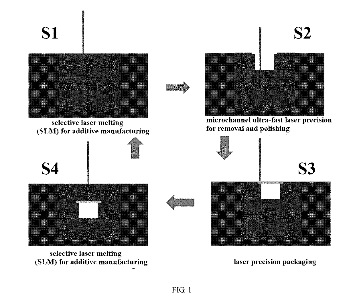
[0051]The preferred embodiments of the present application will be described in detail below with reference to the accompanying drawings. The manufacturing process of the all-laser hybrid additive manufacturing apparatus of the present application is shown in FIG. 1, wherein:

[0052]Step S1, selective laser melting (SLM): 3D printing forming of complex structural parts is performed by using infrared laser;

[0053]Step S2, laser fine removal processing: the groove structure is processed on the 3D printing forming part in step S1 by using ultra-fast laser (femtosecond, picosecond), and the laser polishing and finish are carried on the surface of the groove structure improve the finish of the wall and the bottom surface;

[0054]Step S3, laser precision packaging: the metal piece is placed above the groove structure formed in step S2, and the position where the metal piece is in contact with the groove structure is welded by using infrared laser to be precisely packaged, so that the metal pie...

example 2

[0056]The preferred embodiments of the present application will be described in detail below with reference to the accompanying drawings.

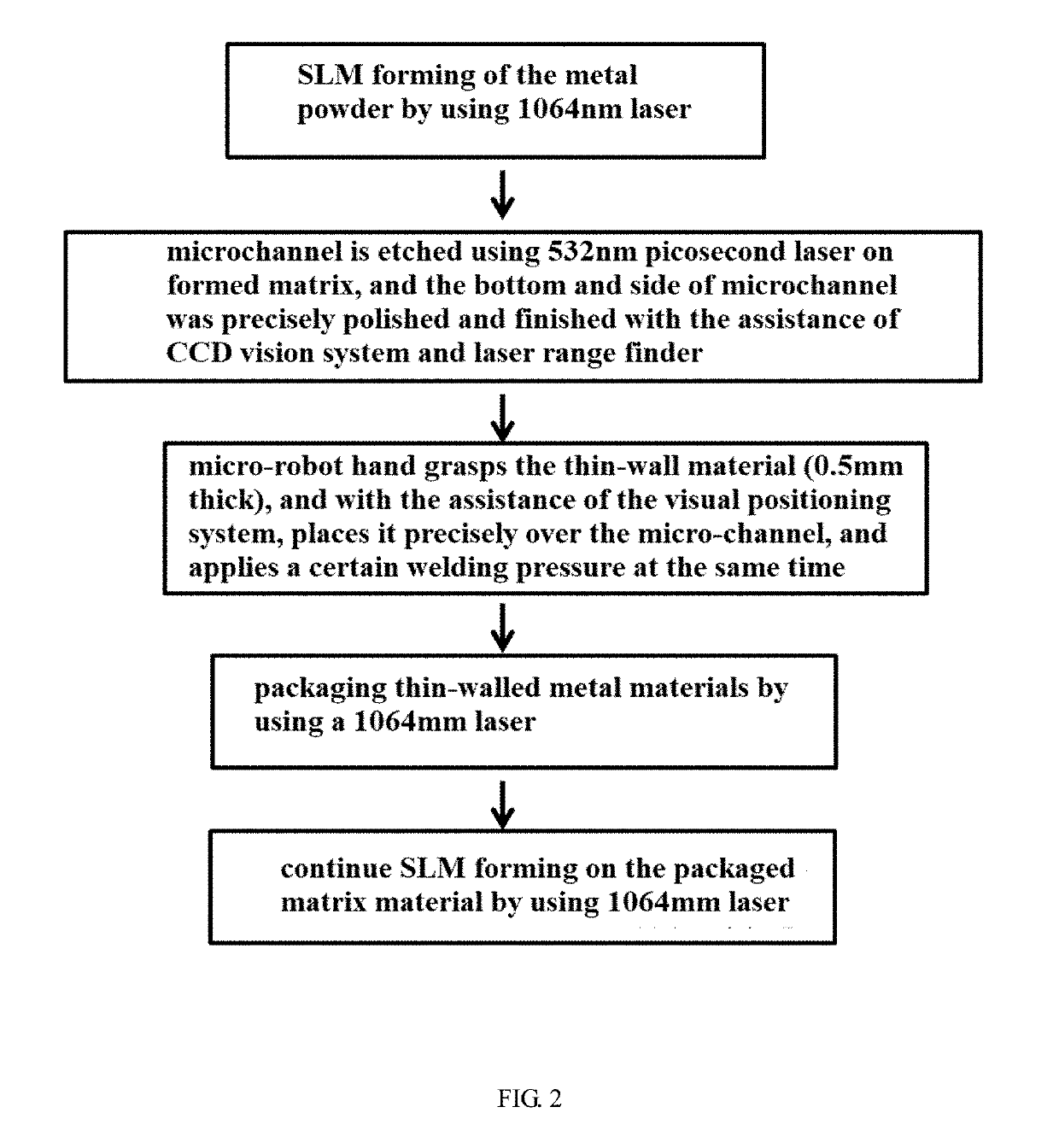
[0057]The one-step microchannel processing flow of the manufacturing process for the all-laser hybrid additive manufacturing apparatus of the present application is shown in FIG. 2.

[0058]Specifically, after the metal powder spreading was completed by the powder spreading system, the SLM forming of the metal powder is carried out by the 1064 nm infrared continuous wave laser.

[0059]Then, with the assistance of the range finder and CCD vision system (CCD detector), the groove structure is processed on the formed part by the 532 nm picosecond green laser, and the laser polishing and finish are carried on the surface of the groove structure to improve the finish of the wall and the bottom surface.

[0060]The micro-robot hand is a set of devices that automatically grab, place and press, and the micro-robot hand grabs and places thin-walled materials, and a...

example 3

[0065]The preferred embodiments of the present application will be described in detail below with reference to the accompanying drawings.

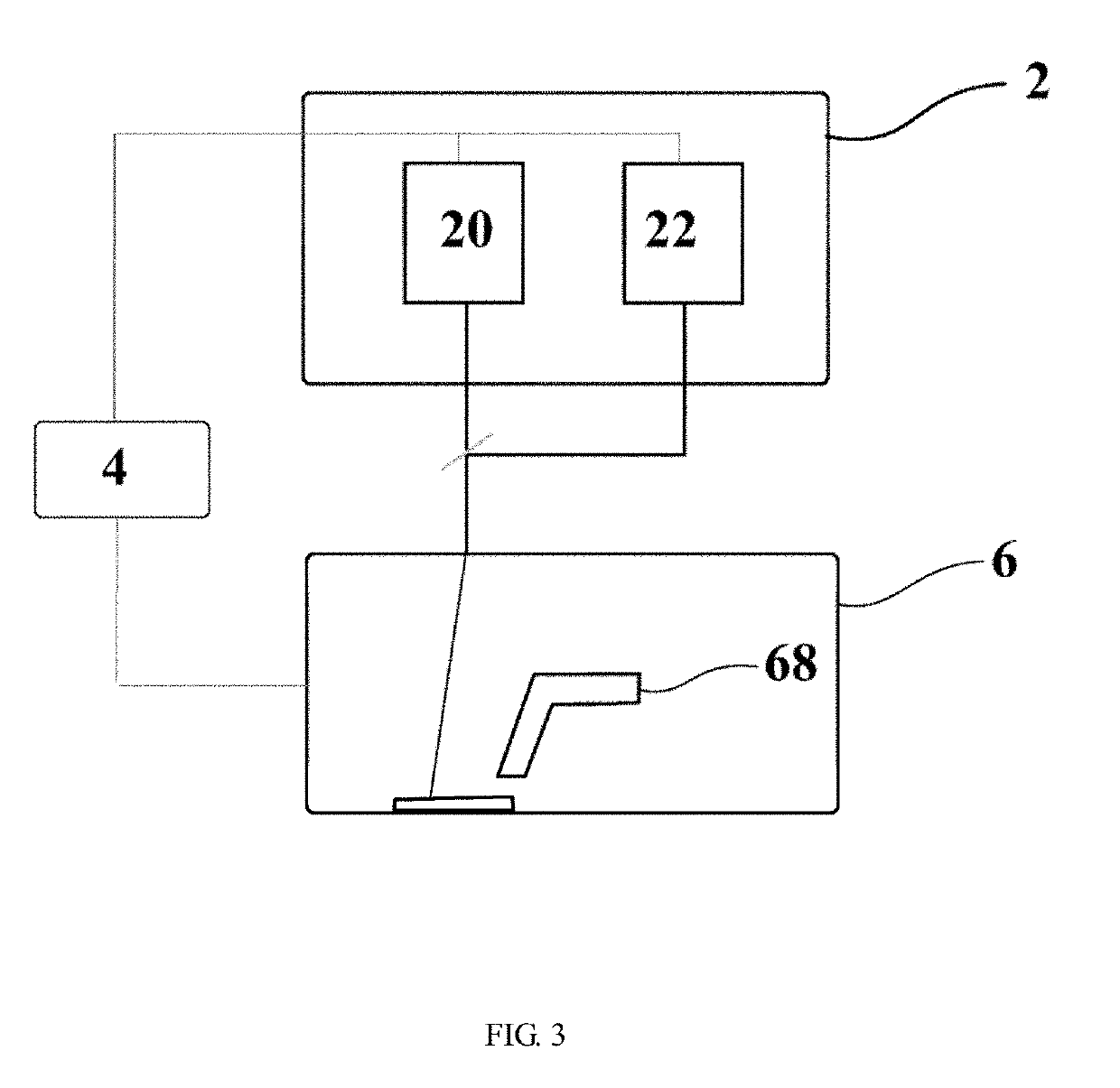
[0066]FIG. 3 is a structural schematic view of an all-laser hybrid additive manufacturing apparatus according to an embodiment of the present application. As shown in FIG. 3, the apparatus comprises: a laser unit 2, a control unit 4 and a forming unit 6. The laser unit 2 is in light path connection with the forming unit 6, and the control unit 4 is electrically connected with the laser unit 2 and the forming unit 6 respectively.

[0067]The laser section 2 includes a laser 20 and a laser 22. The laser 20 is a continuous wave laser and the laser 22 is a short pulse laser.

[0068]The forming unit 6 includes a welding unit 68, and welding unit 68 is controlled by the control unit 4 and is matched with the laser unit 2.

[0069]The laser 20 is additive manufactured at the bottom of the forming unit 6 to produce a product substrate, then the groove structure is...


PUM

PropertyMeasurementUnit
Timeaaaaaaaaaa
Timeaaaaaaaaaa
Nanoscale particle sizeaaaaaaaaaa

Abstract

Disclosed is a method for an all-laser hybrid additive manufacturing. After a matrix is obtained by means of selective laser melting forming, a subtractive forming is carried out on the matrix by means of a pulse laser to form a cavity, and the cavity is then packaged to obtain a forming material with an internal cavity structure. A laser precision packaging method is used in the method based on the melting of the laser selective region. Also disclosed is the apparatus, comprising a laser unit (2), a control unit (4) and a forming unit (6). The laser unit is in light path connection with the forming unit, and the control unit is electrically connected with the laser unit and the forming unit respectively. The laser unit comprises a first laser light source to and a second laser light source. The forming unit comprises a welding unit (68), and the welding unit is controlled by the control unit and is matched with the laser unit for the additive manufacturing.

Description

TECHNICAL FIELD[0001]The present application relates to a material laser processing method, and belongs to the field of material processing.BACKGROUND[0002]Selective Laser Melting technology can realize the formation of complex structural parts, but the forming precision is low, the surface finish is poor, and the resolution is low. Generally, subsequent processing is needed to improve the surface finish. Subsequent processing generally selects two methods. One method is to introduce addition and subtraction materials in additive manufacturing, which can improve the macro-scale finish, but the reliability and durability of the tool are poor, and the resolution is low, especially the processing capability for a microchannel is insufficient. The other one is to introduce ultra-fast laser subtractive technology into laser additive manufacturing, which can realize the precision forming and processing of microchannels of complex internal cavity structures. Both of these methods are faced...

Claims


Application Information

Patent Timeline
IPC IPC(8): B23K26/342B33Y10/00B33Y30/00B33Y40/00B33Y70/00B23K26/06B23K26/0622B23K26/082B23K26/26B23K26/364
CPCB33Y30/00B33Y40/00B33Y10/00B23K26/0624B23K26/0608B23K26/0821H01S3/067B23K26/0643B23K26/364B33Y70/00B23K26/26B23K26/342Y02P10/25B23Q17/2471B23K26/032B23K20/008B23K26/362
Inventor ZHANG, WENWUJIAO, JUNKE
Owner NINGBO INST OF MATERIALS TECH & ENG CHINESE ACADEMY OF SCI
Why Eureka
Try Eureka