
Transceiver with multi-wavelength coexistence

Active Publication Date: 2020-01-09
CHEN PEIJUAN
View PDF13 Cites 4 Cited by
  • Summary
  • Abstract
  • Description
  • Claims
  • Application Information

AI Technical Summary

Benefits of technology

The present invention provides a transceiver that is compact and can accommodate more signal channels compared to prior art. It allows for M×N channel communication through a single transceiver using multi-wavelength coexisting BOSAs. This results in a more efficient and cost-effective solution for optical connectivity. The technical effect of this invention is more compact and versatile optical connectivity with improved channel density and lower costs.

Problems solved by technology

However, this method, which expands an original 4-path wavelength channel to an 8-path wavelength channel, will result in a more complicated design of the WDM multiplexer (MUX) / demultiplexer (deMUX) device, and increase the optical path difference between the eight channels and the manufacturing difficulty; or after the development of the original 4-path optical multiplexer into an 8-path optical multiplexer, further increase the channel insertion loss, and put forward higher requirements for optical path coupling and module manufacturing.
In recent years, many manufacturers have developed a single-fiber bidirectional dual-channel module of cSFP (compact small form-factor pluggable) and even cSFP+in order to improve space utilization, in which each channel is able to receive the receiving and transmitting signals independently; and however, due to manufacturing process limitations, transmitters and receivers of BOSA of this module generally use different wavelengths, which causes the cSFP(+) modules at both ends of the communication system to be paired, so that some inconveniences are brought to the user installation and operation.
Further, when the communication protocol requires that the module must use a same wavelength set (such as the 40 G and 100 G LR4 protocols) to transmit and receive, this technology is helpless.
Therefore, the existing 8-transceiver-channel transceiver generally uses eight wavelengths MUX / deMUX, and is packaged in a larger OSA (such as CFP8), which greatly increases the size and the cost of the optical communication server.

Method used


Image

  • Transceiver with multi-wavelength coexistence
  • Transceiver with multi-wavelength coexistence
  • Transceiver with multi-wavelength coexistence

Examples


Embodiment Construction

[0027]In order to better understand and explain the present invention, the present invention will be further described with accompanying drawings in detail.

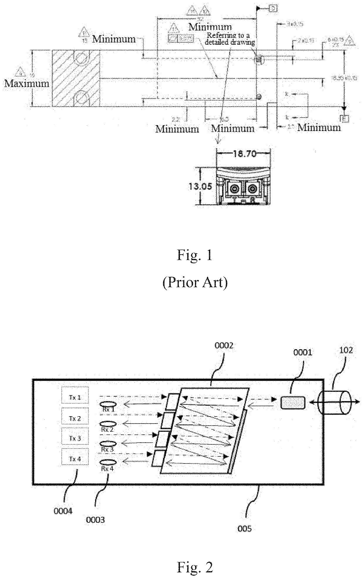
[0028]FIG. 2 is a structurally schematic view of a BOSA (bi-direction optical sub-assembly) which is able to be stacked vertically in a transceiver housing provided by the present invention. Currently, a transceiver with QSFP (quad small form-factor pluggable) package size generally adopts a free space micro-optical device or a planar optical waveguide device to realize a function of internal MUX / deMUX in an OSA. Here, OSA is an abbreviation for optical sub-assembly. If the OSA only has light transmitting function, it is called TOSA (transmitter optical sub-assembly); if the OSA only has light receiving function, it is called ROSA (receiver optical sub-assembly). Moreover, when the OSA has both light transmitting and receiving functions on a single optical interface, it is called BOSA (bi-direction optical sub-assembly).

[0029]As ...


PUM


Abstract

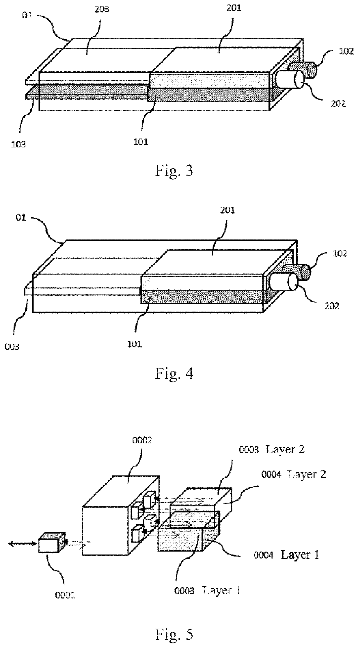
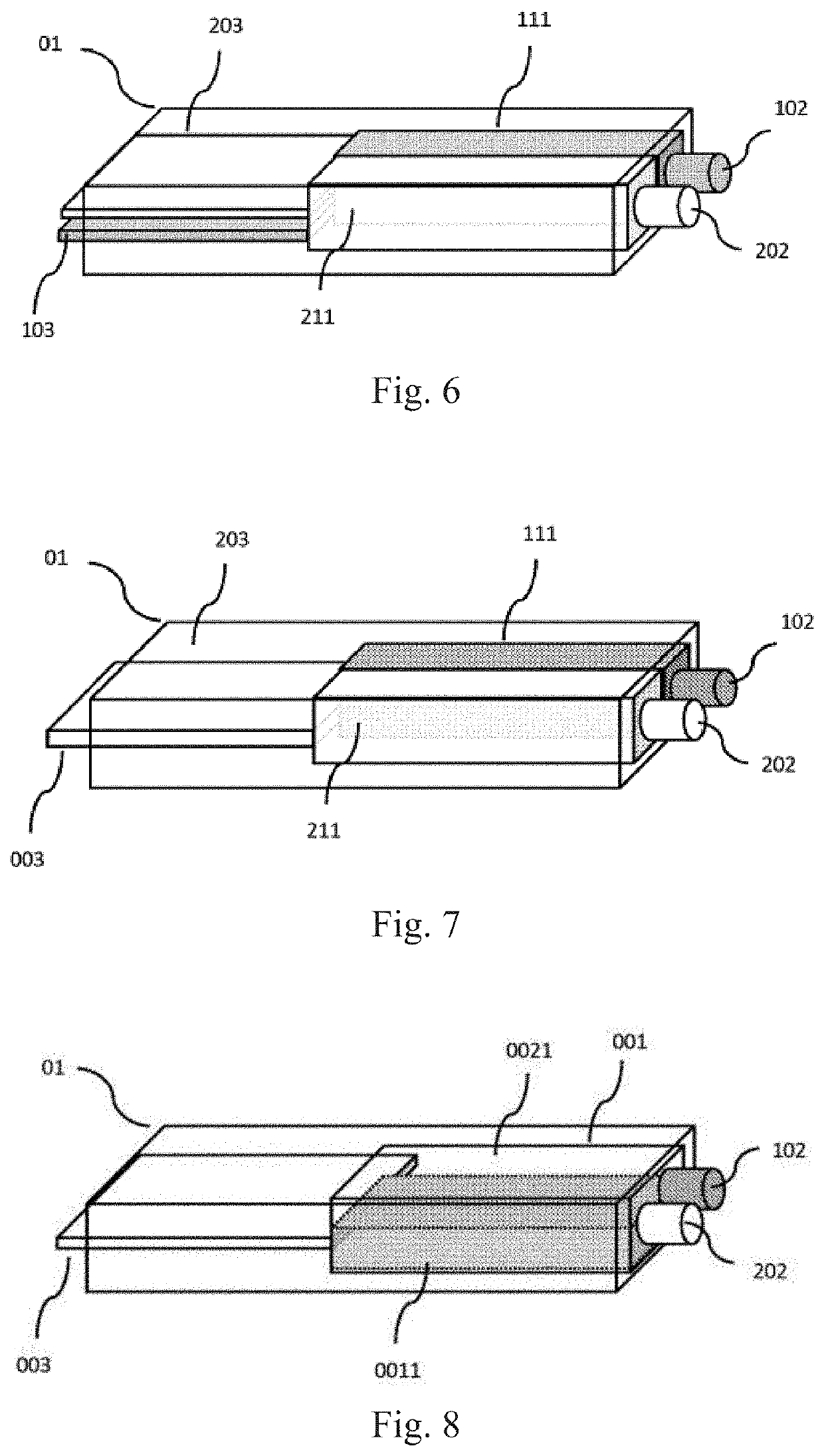
A transceiver with multi-wavelength coexistence is disclosed. A BOSA (bi-direction optical sub-assembly), a PCB (203) and a fiber receptacle (102) are disposed within a transceiver housing; the PCB (203) is horizontally arranged in the transceiver housing; the fiber receptacle (102) is disposed on the BOSA; the BOSA comprises multiple transmitters (0004) and multiple receivers (0003) all of which are optically coupled with the fiber receptacle (102) and electrically connected with the PCB (103); two or more BOSAs, which are stacked in parallel or perpendicular to the PCB (203), are disposed in the transceiver housing and respectively connected with an external fiber through multiple fiber receptacles (102).

Description

CROSS REFERENCE OF RELATED APPLICATION[0001]This is a U.S. National Stage under 35 U.S.C 371 of the International Application PCT / CN2018 / 077187, filed Feb. 26, 2018, which claims priority under 35 U.S.C. 119(a-d) to CN 201710117960.X, filed Mar. 1, 2017 and CN 201720192988.5, filed Mar. 1, 2017.BACKGROUND OF THE PRESENT INVENTIONField of Invention[0002]The present invention relates to the field of optical communication technology, and more particularly to packaging and application of single-fiber multi-wavelength bidirectional optical subassembly (BOSA) in a transceiver.Description of Related Arts[0003]Due to the rapid development of data centers, the industry has put forward a higher and higher requirement for the speed of transceivers. The requirement has promoted the rapid development and expansion of the transceiver industry. Ethernet transceivers are developing at an amazing speed from 10 Gb / s to 40 Gb / s, or even today's 100 Gb / s. Starting from a 40 GE (40 Gb / s Ethernet) module...

Claims


Application Information

Patent Timeline
IPC IPC(8): H04J14/02H04B10/25H04B10/40G02B6/42G02B6/293
CPCH04J14/0213G02B6/4281H04B10/2503G02B6/29386H04B10/40G02B6/4246H04B10/506H04B10/2589G02B6/4215G02B6/29367
Inventor CHEN, PEIJUAN
Owner CHEN PEIJUAN
Learn More