Magnetically enhanced and symmetrical radio frequency discharge apparatus for material processing
a radio frequency discharge and magnetic enhancement technology, applied in the direction of chemical vapor deposition coating, electric discharge tube, coating, etc., can solve the problems of low plasma densities, low plasma densities, and high temperature of substrate heating, so as to improve the effect of plasma densities, smooth exterior surface, and high quality
- Summary
- Abstract
- Description
- Claims
- Application Information
AI Technical Summary
Benefits of technology
Problems solved by technology
Method used
Image
Examples
second embodiment
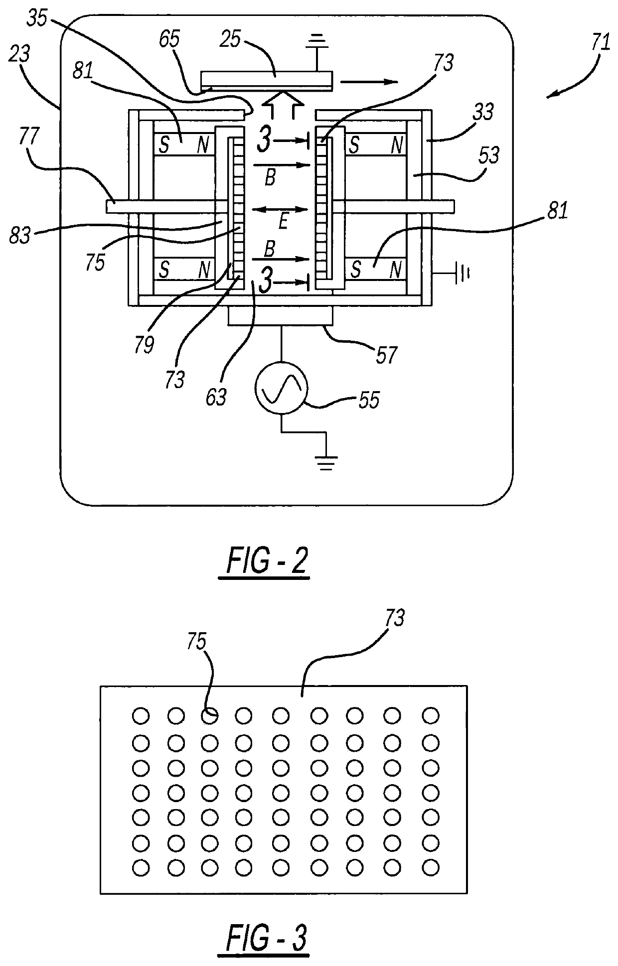
[0028]Reference should now be made to FIGS. 2 and 3 for a magnetically enhanced and symmetrical radio frequency discharge apparatus 71. Apparatus 71 includes vacuum chamber 23, electrically grounded workpiece 25, electrically grounded shield 33, RF source 55 and RF circuit 57, like with the prior embodiment. However, this exemplary embodiment includes a shower head style electrode 73 on each symmetrical side of a longitudinal centerline plane, which are spaced apart from each other across plasma area 63. Each electrode 73 contains multiple holes 75, more preferably at least five holes 75 in each row and in each column, along the generally flat interior surface thereof. These holes 75 are connected to a precursor gas inlet tube 77 via longitudinally and laterally elongated manifold conduits 79. Thus, the precursor gas is emitted through the holes of each electrode in a generally lateral direction which is substantially parallel to magnetic field direction B and electron field directi...
third embodiment
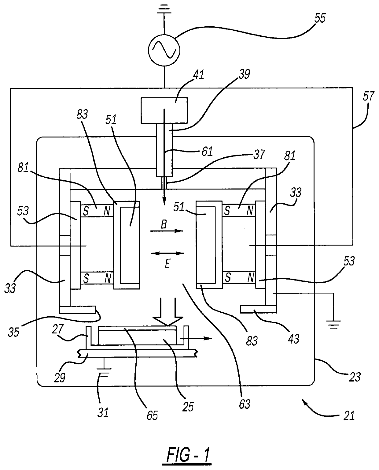
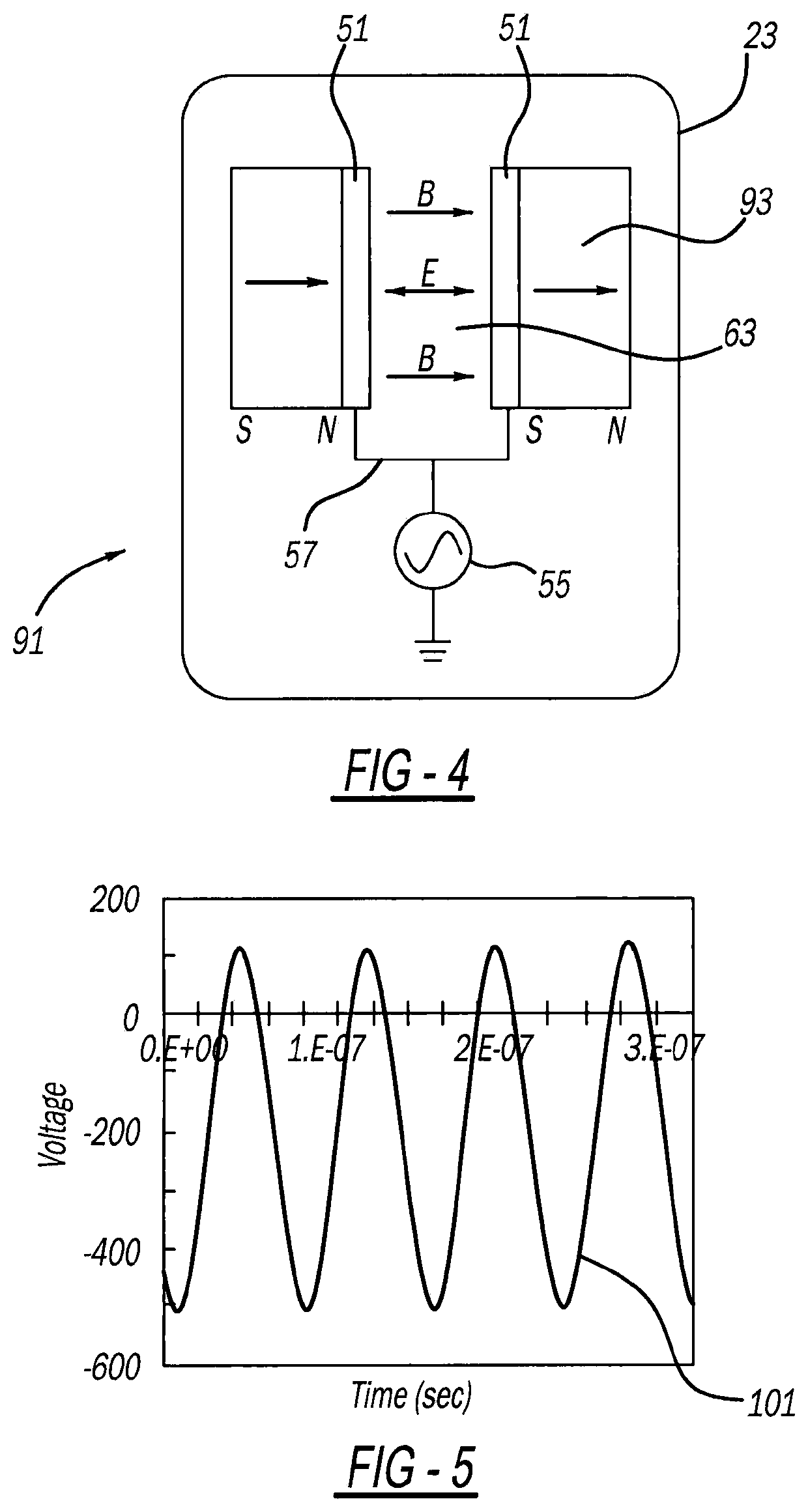
[0030]FIG. 4 illustrates a magnetically enhanced and symmetrical radio frequency discharge apparatus 91. This exemplary construction includes spaced apart electrodes 51 in a vacuum chamber 23 having a precursor gas inlet, grounded shield and grounded workpiece like that of the FIG. 1 embodiment. However, a single enlarged magnet 93 and optional magnetically conductive shunts, are located between each electrode 51 and an insulator. All of electrodes 51 are powered from radio frequency source 55 via circuit 57 like with the prior embodiments such that the primary magnetic field direction B and the primary electrical field direction E are generally parallel to each other laterally spanning across the plasma area 63 and generally perpendicular to a chemical vapor deposition material emission direction toward the workpiece.
[0031]A radio frequency voltage wave form 101 can be observed in FIG. 5. Wave form 101 is obtained from any of the embodiments disclosed hereinabove and compares the v...
fourth embodiment
[0032]a magnetically enhanced and symmetrical radio frequency distribution apparatus 121 can be seen in FIGS. 6-9. RF power source 55 and RF electrical circuit 57 are essentially the same as in the prior embodiments. Multiple annular and spaced apart electrodes 123a and 123b encircle a generally cylindrically shaped and longitudinally elongated quartz housing 125 which defines a vacuum chamber therein. An encircling metallic contact or partial shield 129 is electrically grounded via circuit 127. Structural blocks 131 are secured to housing 125 adjacent ends thereof and longitudinally outboard of electrodes 123a and 123b. Each block 131 preferably contains an annular ring magnet 137, or alternately radially elongated holes within which are located rod magnets. Electrodes 123a and 123b, magnets 137 and contact 129 are all coaxial with each other and surround a longitudinal centerline of the plasma area within housing 125.
[0033]Thus, the primary directions of electrical field E and mag...
PUM
| Property | Measurement | Unit |
|---|---|---|
| distance | aaaaa | aaaaa |
| distance | aaaaa | aaaaa |
| radio frequency power | aaaaa | aaaaa |
Abstract
Description
Claims
Application Information
 - R&D
- Intellectual Property
- Life Sciences
- Materials
- Tech Scout
- Unparalleled Data Quality
- Higher Quality Content
- 60% Fewer Hallucinations
Browse by: Latest US Patents, China's latest patents, Technical Efficacy Thesaurus, Application Domain, Technology Topic, Popular Technical Reports.
© 2025 PatSnap. All rights reserved.Legal|Privacy policy|Modern Slavery Act Transparency Statement|Sitemap|About US| Contact US: help@patsnap.com


