Flyback switching power supply

a power supply and flyback technology, applied in the field of switching power supplies, can solve the problems of discontinuous output current, insufficient calculated number of turns, and low inductance of primary-side windings, and achieve the effects of high conversion efficiency, good emi performance, and relatively good bandwidth

Active Publication Date: 2020-03-12
MORNSUN GUANGZHOU SCI & TECH
View PDF0 Cites 2 Cited by
  • Summary
  • Abstract
  • Description
  • Claims
  • Application Information

AI Technical Summary

Benefits of technology

[0019]The working principle will be illustrated in detail with reference to embodiments. The beneficial effects of the present invention are: leakage inductance between primary and secondary-side wi

Problems solved by technology

This is because the input current is discontinuous and the ripple is relatively large, which has a relatively high requirement for a previous power supply device.
The output current is also discontinuous, and the ripple is large, which has a relatively high requirement for capacity of a subsequent filter capacitor.
The inductance of the primary-side winding is also relatively low, and it is often found that the calculated number of turns is insufficient for winding full a wire casing of a skeleton from left to right in a tiled manner.
At a low working voltage, the series connection causes the inductance to be excessively large, and the sandwich parallel connection scheme has to be used.
Consequently, losses are generated, which makes the efficiency of the switching power supply become low, causing the following problems:
Due to low internal resistance of the winding, it is induced that current caused by the voltages that are not equal is not small, causing losses and relatively large electromagn

Method used


Image

  • Flyback switching power supply
  • Flyback switching power supply
  • Flyback switching power supply

Examples


first embodiment

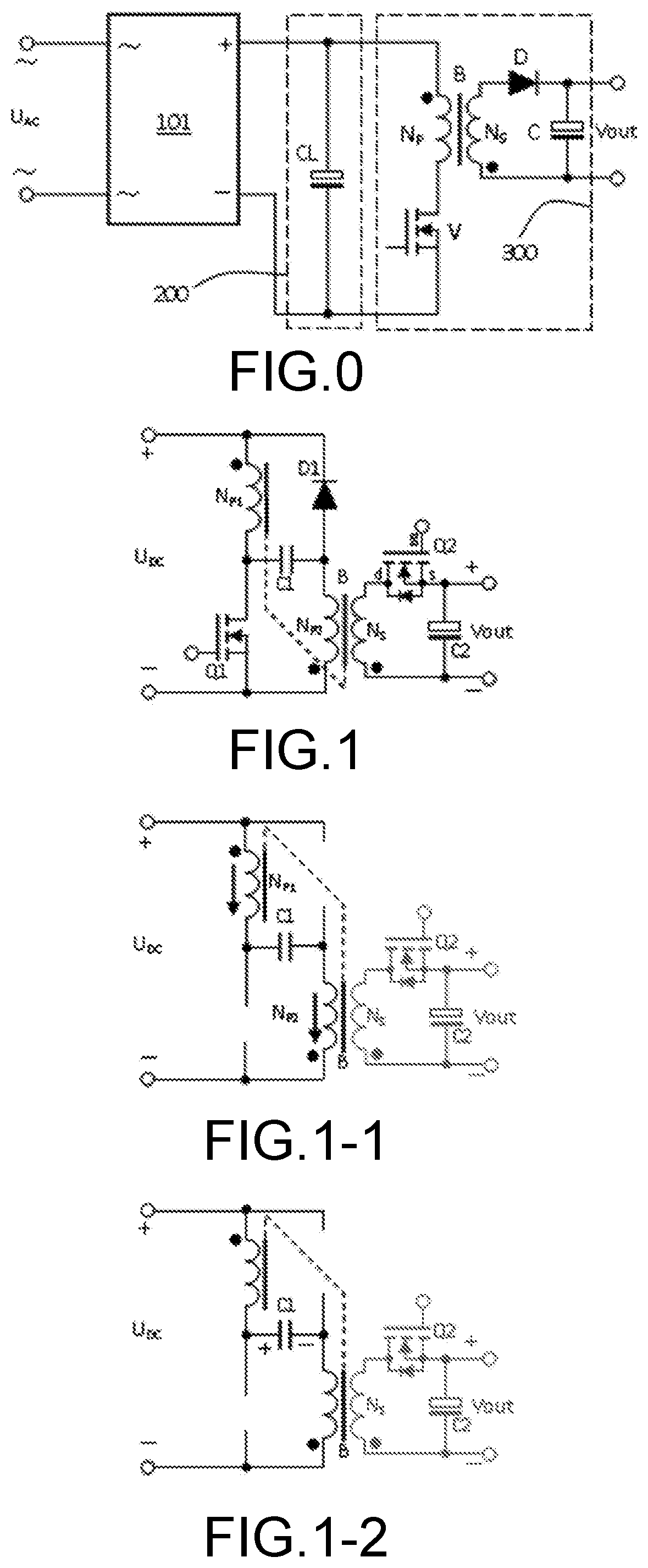
[0035]FIG. 1 is a diagram of a principle of a flyback switching power supply according to a first embodiment of the present invention. The flyback switching power supply includes a transformer B, a first switch transistor Q1, and a second switch transistor Q2, where the first switch transistor Q1 and the second switch transistor Q2 are both N-channel field-effect transistors, a second capacitor C2, and a first diode D1. The transformer B includes a first primary-side winding NP1, a second primary-side winding NP2, and a secondary-side winding NS. An undotted terminal of the secondary-side winding NS is connected to a drain d of the second switch transistor Q2, and a source s of the second switch transistor Q2 is connected to one end of the second capacitor C2, to form positive output, which is the +end of Vout in the figure. A dotted terminal of the secondary-side winding NS is connected to the other end of the second capacitor C2, to form negative output, which is the −end of Vout ...

second embodiment

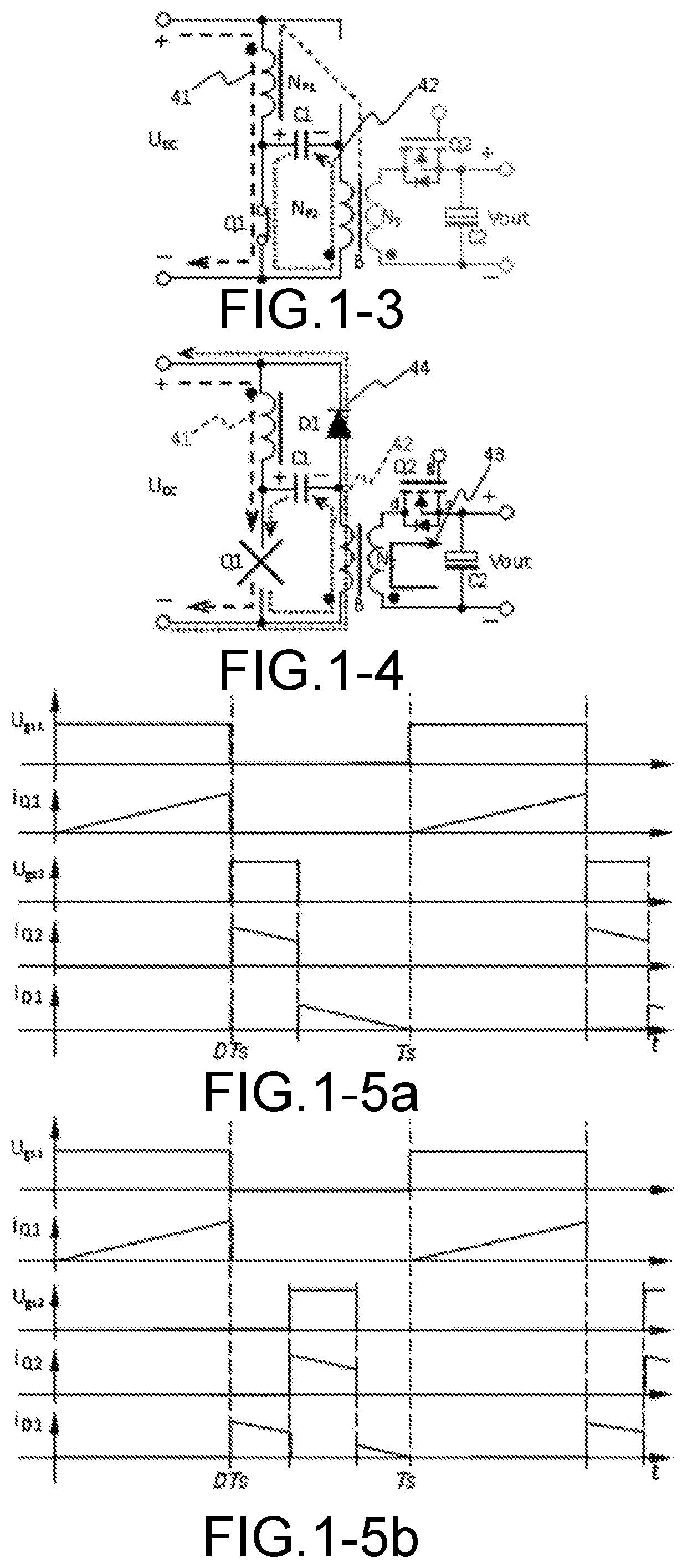
[0072]The present invention further provides an equivalent solution of the first embodiment, corresponding to solution 2. Referring to FIG. 2, a flyback switching power supply, including a transformer B, a first switch transistor Q1, a second switch transistor Q2, where the first switch transistor Q1 and the second switch transistor Q2 are both N-channel field-effect transistors, a second capacitor C2, and a first diode D1, where the transformer B includes a first primary-side winding NP1, a second primary-side winding NP2, and a secondary-side winding NS. An undotted terminal of the secondary-side winding NS is connected to a drain d of the second switch transistor Q2, and a source s of the second switch transistor Q2 is connected to one end of the second capacitor C2, to form positive output, which is the +end of Vout in the figure. A dotted terminal of the secondary-side winding NS is connected to the other end of the second capacitor C2, to form negative output, which is the −en...

third embodiment

[0088]Referring to FIG. 3, also the foregoing solution 3, a flyback switching power supply, including a transformer B, a first switch transistor Q1, a second switch transistor Q2, where the first switch transistor Q1 is a P-channel field-effect transistor, and the second switch transistor Q2 is an N-channel field-effect transistor, a second capacitor C2, and a first diode D1, where the transformer B includes a first primary-side winding NP1, a second primary-side winding NP2, and a secondary-side winding NS. An undotted terminal of the secondary-side winding NS is connected to a drain d of the second switch transistor Q2, and a source s of the second switch transistor Q2 is connected to one end of the second capacitor C2, to form positive output, which is the +end of Vout in the figure. A dotted terminal of the secondary-side winding NS is connected to the other end of the second capacitor C2, to form negative output, which is the −end of Vout in the figure. A negative terminal− of ...


PUM


Abstract

A flyback switch power supply connects NP1 heteronymous terminals in a transformer B to a power source, grounds second primary side winding NP2 heteronymous ends, and ensures that NP1 and NP2 are dual-wire parallel windings. Adding a capacitor C1, one end of C1 is connected to NP1 homonymous terminals, and the other end is connected to NP2 homonymous terminals. The secondary side winding uses a Q2 connection method that is the opposite to the prior art, and is controlled by a PWM signal controlled by another output voltage. The following effect is realized: when Q1 is connected, NP1 and NP2 are both excited, and there is artificial surplus energy; when Q1 is disconnected, the secondary side NS implements a rectified output voltage via Q2 on the basis of the output load requirements, and the leakage inductance and excess energy are non-destructively absorbed by NP2 via D1.

Description

TECHNICAL FIELD[0001]The present invention relates to the field of switching power supplies, and in particular, to a flyback switching power supply.BACKGROUND ART[0002]At present, switching power supplies have been extensively used. For applications with input power below 75 W and having no requirement on power factor (PF), flyback switching power supplies may have fascinating advantages: a simple circuit topology and a wide input voltage range. Since the number of components is small, the reliability of the circuit is relatively high, and the flyback switching power supply is widely used. For convenience, in many documents, the flyback switching power supply is also referred to as a flyback switching power supply, a flyback power supply, and a flyback converter. In Japan and Taiwan, it is also referred to as a flyback converter, a flyback switching power supply, and a flyback power supply. A common topology for AC / DC converters is shown in FIG. 0. The prototype of the figure is fro...

Claims


Application Information

Patent Timeline
IPC IPC(8): H02M3/335H02M1/44
CPCH02M1/44H02M3/33576H02M3/33523H02M3/33592H02M1/0064
Inventor WANG, BAOJUN
Owner MORNSUN GUANGZHOU SCI & TECH
Why Eureka
Try Eureka