
Armored Rigging System

Pending Publication Date: 2020-03-26
CAMPBELL RICHARD V
View PDF5 Cites 1 Cited by
  • Summary
  • Abstract
  • Description
  • Claims
  • Application Information

AI Technical Summary

Benefits of technology

This invention is about a flexible tensile member that can be used to rig heavy machines in industries like mining. It has a strong core and an armor layer that protects it from external forces and blows. This makes it lightweight and has excellent strength in tension. The armor layer can take different forms, like a hollow cylinder with a thick wall. This invention provides a safer and stronger way to rig heavy machines, making them more efficient and durable.

Problems solved by technology

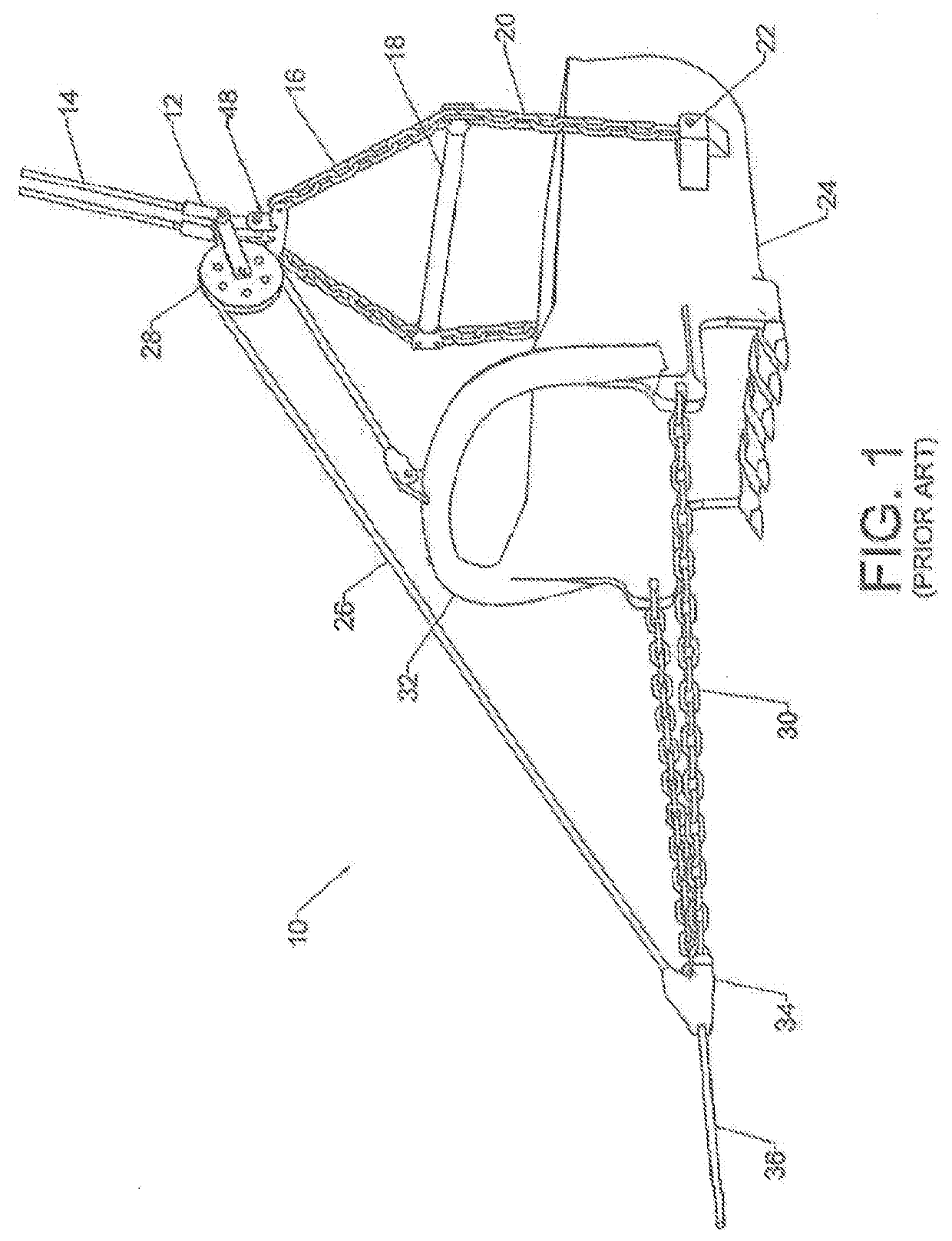
The bucket itself often weighs many tons.
The bucket assembly is operated in a brutal environment.
Such chains are quite heavy.
The size and weight of the chains make them difficult and dangerous to handle.
In addition, the chains rapidly elongate while in use—primarily because of link-to-link abrasion.
This elongation alters the dumping geometry of the bucket assembly and reduces its performance.
In addition to the hostile environment created by dropping, dragging, and lifting the bucket, one must also consider the hazards of deliberately laying the assembly on the ground.
The spreader bar may weigh several tons and even the dump block assembly may exceed one ton in weight.
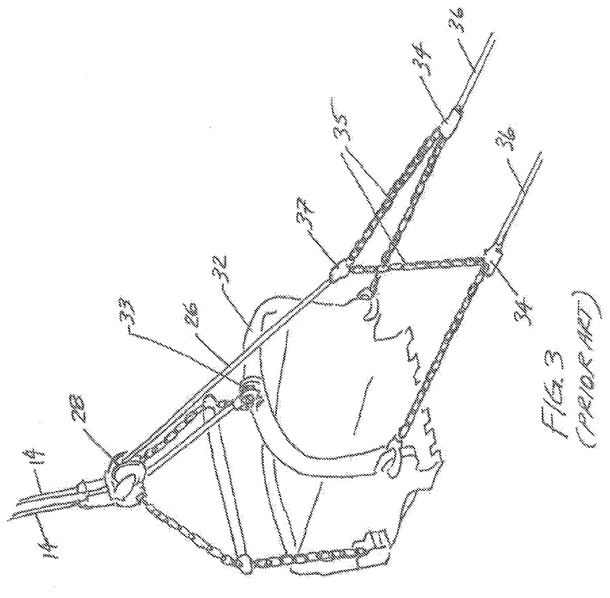
Thus, the reader will perceive that even though the tensile members in the upper and / or lower hoist assemblies lie above the dropping and digging operations, they are still subjected to extreme battering, bending, cutting, and compression forces when the bucket is laid down.
Further, the orientation of the “pile” of heavy components created when the bucket is laid down is random and impossible to consistently predict.
Thus, even though it is possible to use a flexible tensile member in the hoist assembly, a conventional flexible tensile member is not likely to survive the full range of bucket operations.
Some flexible designs have been evaluated over the years but no such design has ever been able to successfully compete with chain.
However, one must bear in mind the hostile environment in which this type of machine operates.
The hostile environment makes the use of light-weight flexible tensile members difficult.

Method used


Image

  • Armored Rigging System
  • Armored Rigging System
  • Armored Rigging System

Examples


Embodiment Construction

[0130]FIG. 6 shows a cross section of an armored tensile member made according to the present invention. Stranded core 54 carries the tensile bad. This stranded core preferably comprises advanced synthetic filaments. Examples of such advanced synthetic filaments include DYNEEMA, SPECTRA, TECHNORA, TWARON, KEVLAR, VECTRAN, PBO, carbon fiber, and glass fiber. In general the individual filaments have a thickness that is less than that of human hair. The filaments are very strong in tension, but they are not resistant to battering and cutting forces. Hence, they have not traditionally been used in hostile environments such as the mining industry.

[0131]The core in the example of FIG. 6 includes seven separate strands (six strands around one center strand). Each of these strands include the aforementioned synthetic filaments. The strands are often braided or twisted into a known pattern. They may also contain more traditional constituents (such as steel wires). A cable or strand including...


PUM

PropertyMeasurementUnit
Weightaaaaaaaaaa
Thicknessaaaaaaaaaa
Diameteraaaaaaaaaa

Abstract

An assembly and method for using a flexible tensile member as part of the rigging for a heavy machine such as those used in the mining industry. The inventive tensile member includes a core surrounded by a separate armor layer. The armor layer assumes various forms, including a hollow cylinder having a substantial wall thickness. The core produces excellent strength in tension (and with a substantial reduction in weight). The armor layer protects the core from external blows and forces produced by the weight of the other parts of the machine's rigging and the hostile environment in which the machine operates.

Description

CROSS-REFERENCES TO RELATED APPLICATIONS[0001]This non-pro visional patent application claims the benefit of multiple prior applications. These prior applications are U.S. Pat. App. Ser. No. 62 / 694,079 anti U.S. Pat. App. Ser. No. 62 / 694,069, both filed on Jul. 5, 2018. BACKGROUND OF THE INVENTION1. Field of the Invention[0002]This invention relates to the field of mining and excavation equipment. More specifically, the invention comprises an improved tensile member for such machinery that reduces the need for wire rope and heavy chains.2. Description of the Related Art[0003]In order to understand the significance of the present invention, it is important to have some understanding of conventional mining and excavation machinery. FIG. 1 shows dragline bucket assembly 10. As those skilled in the art will know, the dragline bucket assembly is lifted and positioned by a boom crane—typically a very large boom crane. Bucket 24 is usually made of thick steel. The width of the bucket's mou...

Claims


Application Information

Patent Timeline
IPC IPC(8): D07B1/16D07B1/04
CPCD07B2201/2083E02F3/58D07B2401/2075D07B2201/1016E02F3/48D07B1/162D07B1/04D07B2501/2015D07B2201/2086D07B1/18D07B5/006D07B2201/2091F16G11/042F16G11/025E02F3/65
Inventor CAMPBELL, RICHARD V.
Owner CAMPBELL RICHARD V
Features
  • Generate Ideas
  • Intellectual Property
  • Life Sciences
  • Materials
  • Tech Scout
  • Unparalleled Data Quality
  • Higher Quality Content
  • 60% Fewer Hallucinations
Learn More