Multilayer ceramic capacitor
a multi-layer ceramic and capacitor technology, applied in the direction of fixed capacitors, stacked capacitors, fixed capacitor details, etc., can solve the problem of insufficient suppression of achieve the effect of suppressing the degradation of the insulation resistance and suppressing the migration of oxygen vacancies
- Summary
- Abstract
- Description
- Claims
- Application Information
AI Technical Summary
Benefits of technology
Problems solved by technology
Method used
Image

Examples
first embodiment
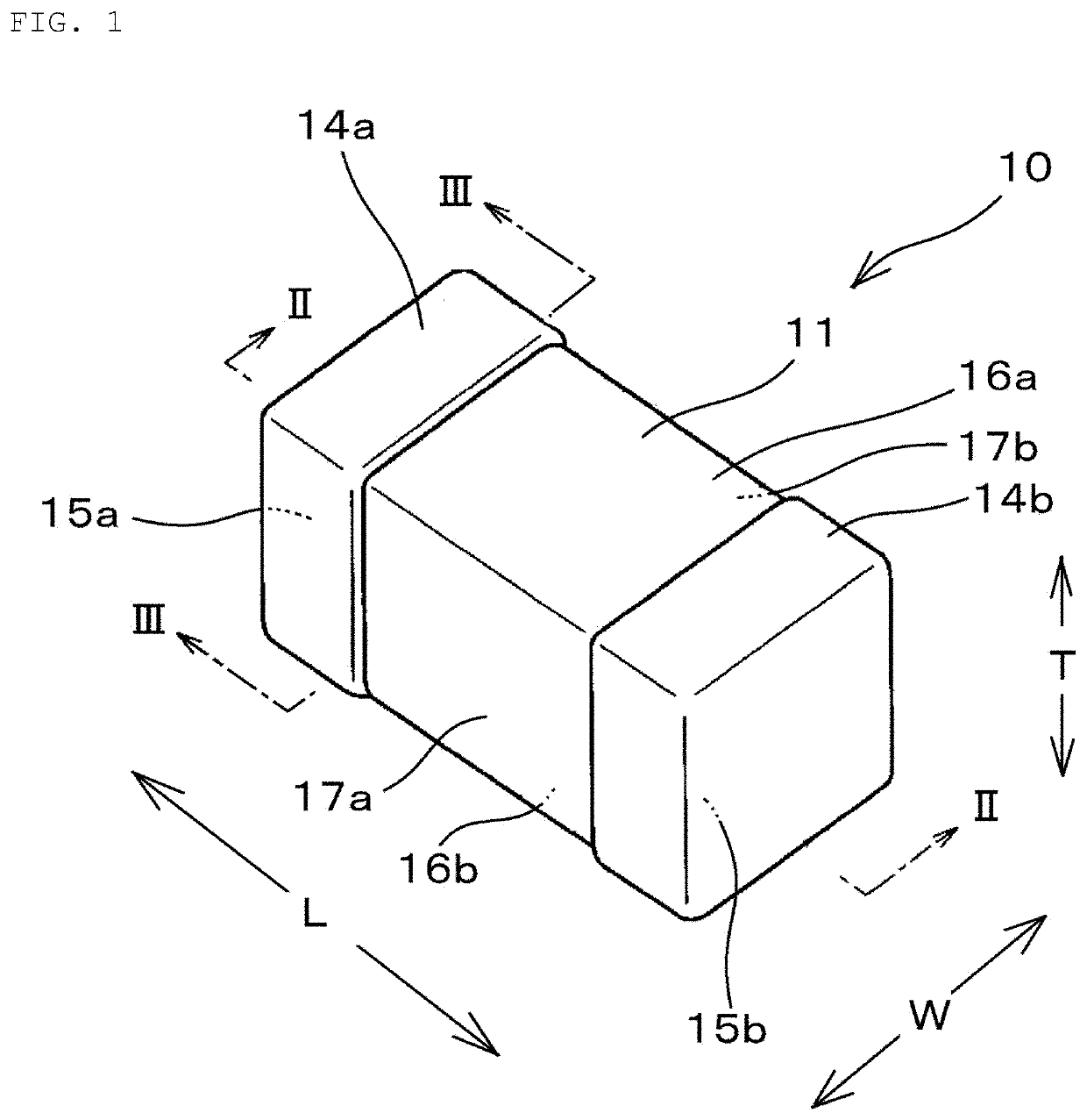
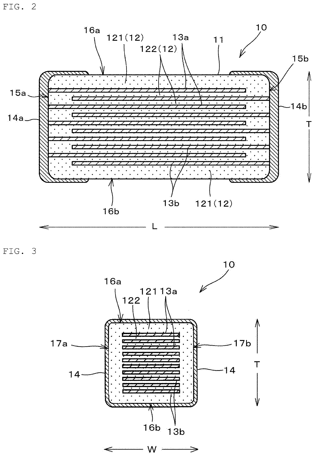
[0028]FIG. 1 is a perspective view of a multilayer ceramic capacitor 10 according to a first embodiment. FIG. 2 is a sectional view along a line II-II of the multilayer ceramic capacitor 10 shown in FIG. 1. FIG. 3 is a sectional view along a line III-III of the multilayer ceramic capacitor 10 shown in FIG. 1.
[0029]As shown in FIGS. 1 to 3, the multilayer ceramic capacitor 10 is an electronic component having a rectangular parallelepiped as a whole and includes a laminate 11 and a pair of external electrodes 14 (14a and 14b). The pair of external electrodes 14 (14a and 14b) are disposed opposite to each other as shown in FIG. 1.
[0030]Here, a direction in which the pair of external electrodes 14 are opposite to each other is defined as a length direction L of the multilayer ceramic capacitor 10, a stacking direction of internal electrodes 13 (13a and 13b) described later is defined as a thickness direction T, and a direction perpendicular to both the length direction L and the thickne...
example
[0089]A first dielectric raw material formulation to be first crystal grains were prepared by a following method.
[0090]First, BaTiO3 was weighed and then wet-blended by a ball mill to crush an aggregate.
[0091]Next, the low-crystallinity BaTiO3 was blended with component materials to be added, with the components to be added and the addition amounts of the components represented by a following composition formula, and mixed by a ball mill, with water used as a medium. Thereafter, the resultant mixture was subjected to evaporative drying to give a first dielectric raw material formulation.
100BamTiO3+aDy2O3+bMgO+cMn+dSiO2+eV2O5 Composition formula:
[0092]In the composition formula, m=1.0070, a=5.0, b=0.08, c=0.56, d=1.0, and e=0.1.
[0093]As the component materials to be added, BaCO3, Dy2O3, MgCO3, MnCO3, SiO2, and V2O5 were used.
[0094]A second dielectric raw material formulation to be second crystal grains were also prepared by a following method.
[0095]First, BaTiO3 having higher crysta...
second embodiment
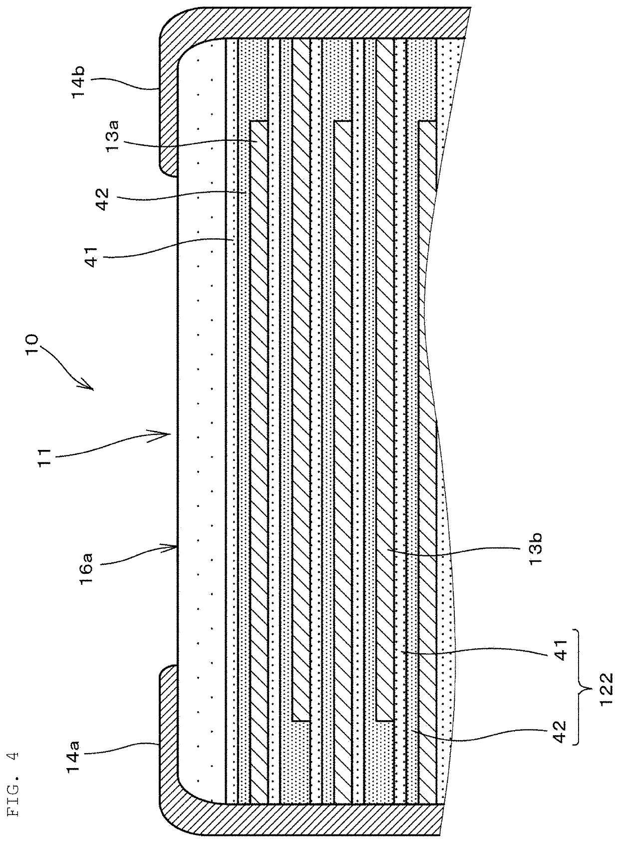
[0114]In the multilayer ceramic capacitor 10 according to the first embodiment, the inner dielectric layer 122 of the dielectric layer 12 is formed of the two layers, i.e., the first grain layer 41 and the second grain layer 42.
[0115]On the other hand, in a multilayer ceramic capacitor according to a second embodiment, the inner dielectric layer 122 of the dielectric layer 12 is formed of three layers, i.e., the second grain layer 42, the first grain layer 41, and the second grain layer 42.
[0116]FIG. 5 is a partially enlarged view of a section of a multilayer ceramic capacitor 10A according to the second embodiment and is a schematic sectional view for illustrating a detailed configuration of the dielectric layer 12. As shown in FIG. 5, the inner dielectric layer of the dielectric layer 12 is formed of the three layers, i.e., the second grain layer 42, the first grain layer 41, and the second grain layer 42. Specifically, the three layers are configured so that the first grain layer...
PUM
| Property | Measurement | Unit |
|---|---|---|
| thickness | aaaaa | aaaaa |
| grain size | aaaaa | aaaaa |
| grain size | aaaaa | aaaaa |
Abstract
Description
Claims
Application Information
 - R&D Engineer
- R&D Manager
- IP Professional
- Industry Leading Data Capabilities
- Powerful AI technology
- Patent DNA Extraction
Browse by: Latest US Patents, China's latest patents, Technical Efficacy Thesaurus, Application Domain, Technology Topic.
© 2024 PatSnap. All rights reserved.Legal|Privacy policy|Modern Slavery Act Transparency Statement|Sitemap