
Variable frequency drive with integral machine condition monitoring and protection system

a technology of machine condition monitoring and protection system, applied in the direction of single motor speed/torque control, software algorithm control, electrical apparatus, etc., can solve the problems of premature failure of winding insulation, motor bearings to heat and fail without any indication, and achieve the effect of avoiding production loss and expensive machine repair costs

Inactive Publication Date: 2020-04-09
TREHIN HARNAM SINGH
View PDF2 Cites 1 Cited by
  • Summary
  • Abstract
  • Description
  • Claims
  • Application Information

AI Technical Summary

Benefits of technology

The present invention is a variable frequency drive (VFD) that has a system to protect and monitor machines. It allows for continuous adjustment of VFD parameters to optimize the machine's operation. The invention also informs the machine operator about its condition, which can prevent breakdowns and reduce production losses and repair costs.

Problems solved by technology

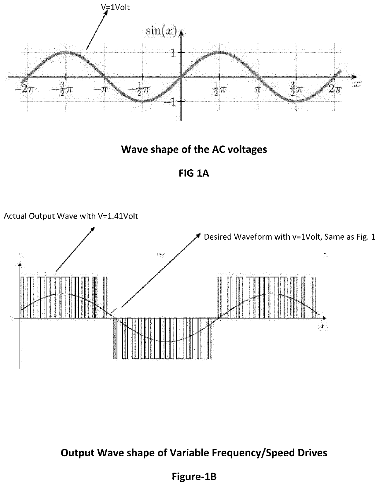
However, VFDs can cause damages to motors, including premature failure of the winding insulation, which may occur when motors are designed for sinusoidal wave forms but the VFD output voltages are square waves with 1.42 times the root mean square value of the nominal AC voltages for which the motors are designed.
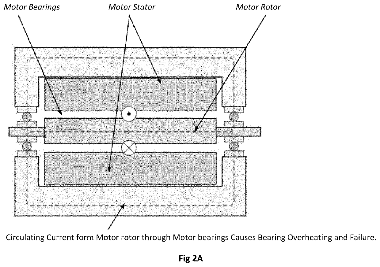
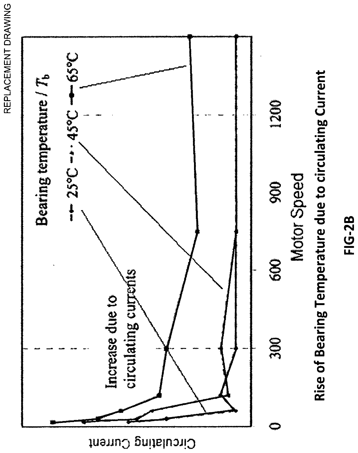
Further problems of using VFDs is because of the high frequency switching of power devices, circulating currents are established within the motor frame and bearings, which causes the motor bearings to heat and fail without any indication.
Yet another problem of using VFDs is that when a motor speed is near or at the natural mechanical frequency of the system, high amplitude oscillations (i.e., resonance) can cause severe mechanical damage, which requires the avoidance of operation at those speeds.
Last, a machine's health continues to deteriorate due to various factors including aging, operating conditions, little to no maintenance, and environmental factors.
As the above unfavorable conditions go unnoticed, the machine breaks down and manufacturing processes are shut.
The owner ends up with a loss of production and high repair costs.

Method used


Image

  • Variable frequency drive with integral machine condition monitoring and protection system
  • Variable frequency drive with integral machine condition monitoring and protection system
  • Variable frequency drive with integral machine condition monitoring and protection system

Examples


Embodiment Construction

[0017]It will be readily understood that the components of the embodiments as generally described and illustrated in the figures herein, may be arranged and designed in a wide variety of different configurations in addition to the described example embodiments. Thus, the following more detailed description of the example embodiments, as represented in the figures, is not intended to limit the scope of the embodiments, as claimed, but is merely representative of example embodiments.

[0018]Furthermore, the described features, structures, or characteristics may be combined in any suitable manner in one or more embodiments. In the following description, numerous specific details are provided to give a thorough understanding of embodiments. One skilled in the relevant art will recognize, however, that the various embodiments can be practiced without one or more of the specific details, or with other methods, components, materials, etc. In other instances, well-known structures, materials,...


PUM


Abstract

The present invention provides a variable frequency drive (VFD) which has an integral machine monitoring and protection system to allow continual adjustment of VFD parameters for the optimized operation of a machine. The invention also includes a mentoring and control system provided with self-learning software module. This software module will collect real-time data and stores in the local data-base. When sufficient data is collected the system can be put into the fully or semi-automatic mode. In automatic mode, the system will automatically make decision and adjust operating parameters to operate safely. In semi-automatic mode the system will send new adjustment values / set points for operator to make a decision.

Description

BACKGROUND[0001]Controlling the operation speed of machinery has long been a goal of industry, in order to allow the machine to be used in more processes as well as for energy conservation. Usually, in the event a machine's speed needs to be adjusted, variable speed controllers are used. In most circumstances, when a machine is driven by an AC motor, variable frequency drives (VFD) are used due to the speed of an AC motor being directly proportional to the frequency of the AC power supplied to the motor.[0002]The method for implementation by manufacturers of VFD is similar to converting constant DC bus voltages to variable voltage and variable frequency output to control the speed of the AC motor. However, VFDs can cause damages to motors, including premature failure of the winding insulation, which may occur when motors are designed for sinusoidal wave forms but the VFD output voltages are square waves with 1.42 times the root mean square value of the nominal AC voltages for which ...

Claims


Application Information

Patent Timeline
Patent Type & Authority Applications(United States)
IPC IPC(8): H02P27/06H02P29/024H02P6/08H02P23/00H02M5/458
CPCH02P23/0077H02M2001/0025H02M5/458H02P27/06H02P29/024H02P6/08H02P27/04H02M1/007H02M1/0025
Inventor TREHIN, HARNAM SINGH
Owner TREHIN HARNAM SINGH
Learn More