Thermoelectric module with integrated printed circuit board

Active Publication Date: 2020-08-20
GENTHERM INC
View PDF0 Cites 6 Cited by
  • Summary
  • Abstract
  • Description
  • Claims
  • Application Information

AI Technical Summary

Benefits of technology

The patent text describes a thermoelectric module assembly and system for thermally conditioning components. The assembly includes a printed circuit board and a plurality of thermoelectric devices, each with a thermally conductive plate and thermoelectric elements. The thermoelectric devices are mechanically coupled to the printed circuit board. The system also includes a printed circuit board with electrical conduits and a plurality of thermoelectric devices in thermal communication with the electrical conduits. The thermoelectric devices are in electrical communication with at least one thermal sensor on the printed circuit board or the thermoelectric devices. The method of fabricating the thermoelectric module assembly involves mechanically coupling the thermoelectric devices to the printed circuit board. The technical effects of the patent text include improved thermal control of components and efficient use of thermoelectric technology.

Problems solved by technology

Power electronics and other electrical devices, such as batteries, can be sensitive to overheating, cold temperatures, extreme temperatures, and operating temperature limits.
The performance of such devices may be diminished, sometimes severely, when the devices are operated outside of recommended temperature ranges.
In semiconductor devices, integrated circuit dies can overheat and malfunction.
In batteries, including, for example, batteries used for automotive applications in electrified or electrical vehicles, battery cells and their components can degrade when overheated or overcooled.
Such degradation can manifest itself in reduced battery storage capacity and / or reduced ability for the battery to be recharged over multiple duty cycles.

Method used


Image

  • Thermoelectric module with integrated printed circuit board
  • Thermoelectric module with integrated printed circuit board
  • Thermoelectric module with integrated printed circuit board

Examples


Embodiment Construction

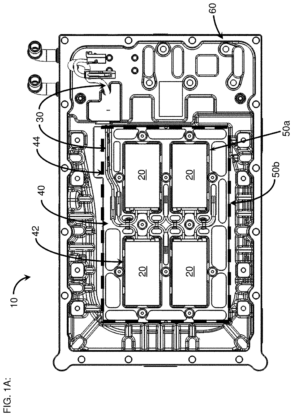
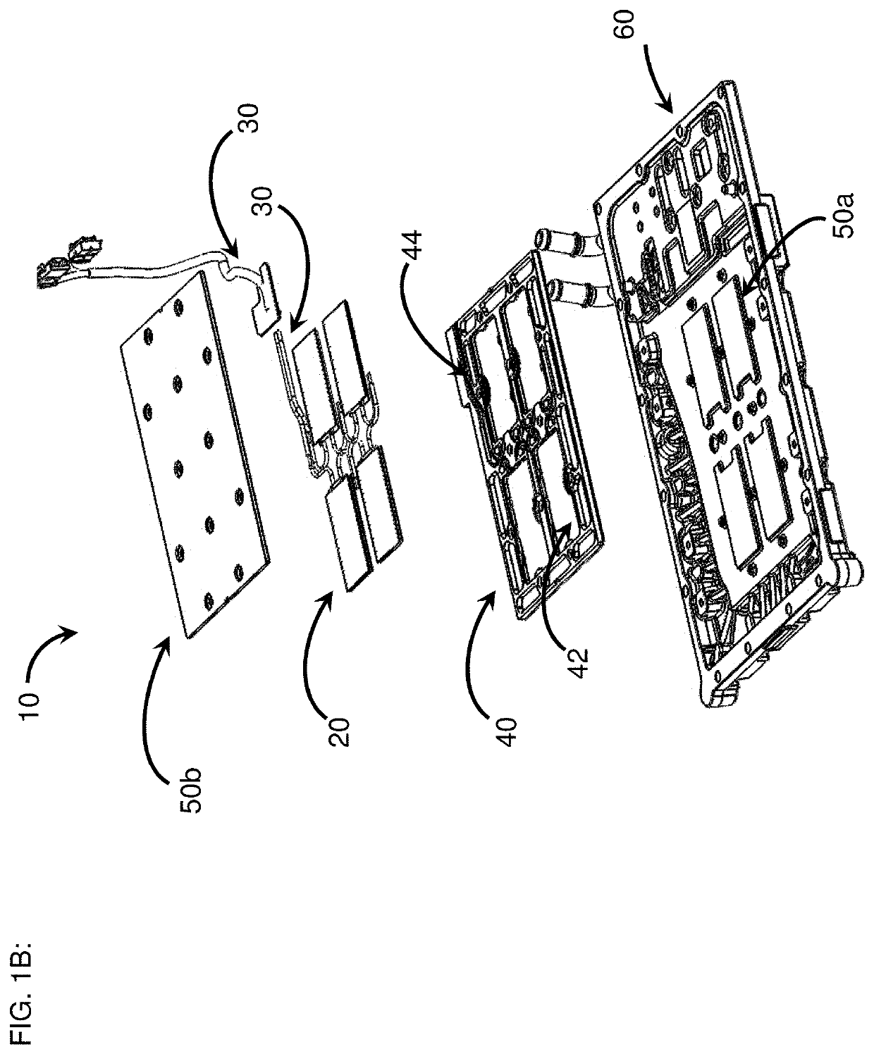
[0025]FIGS. 1A and 1B schematically illustrate a top view and an exploded view, respectively, of a portion of a thermoelectric module assembly 10 comprising a plurality of thermoelectric devices 20 that are electrically interconnected with one another and to external circuitry by electrically conductive wires 30. The thermoelectric devices 20 are held in place (e.g., aligned and secured) by a molded plastic insert 40 with a plurality of holes 42 configured to receive and hold the thermoelectric devices 20 onto a first heat spreader 50a and below a second heat spreader 50b, the first heat spreader 50a in thermal communication with the cooling plate 60 (e.g., heat exchanger) of the thermoelectric module assembly 10. The plastic insert 40 also has a plurality of channels 44 configured to receive and hold the electrically conductive wires 30. Fabrication of the thermoelectric module assembly 10 of FIGS. 1A and 1B can be challenging and time-consuming since each of the thermoelectric dev...


PUM

PropertyMeasurementUnit
Timeaaaaaaaaaa
Thicknessaaaaaaaaaa
Poweraaaaaaaaaa

Abstract

A thermoelectric module assembly for thermally conditioning a component is includes first and second heat spreaders spaced apart from one another and at least one thermoelectric sub-assembly between and in thermal communication with the first and second heat spreaders. The at least one thermoelectric sub-assembly includes a plurality of thermoelectric devices and a printed circuit board having a plurality of electrical conduits. Each of the thermoelectric devices has a first end portion and a second end portion, the second end portion opposite from the first end portion, the first end portion mechanically coupled to the printed circuit board and in electrical communication with the plurality of electrical conduits, and the second end portion spaced from the printed circuit board.

Description

CLAIM OF PRIORITY[0001]This application claims the benefit of priority to U.S. Provisional Appl. No. 62 / 808,205 filed Feb. 20, 2019 and incorporated in its entirety by reference herein.BACKGROUNDField[0002]This application relates to thermoelectric devices and modules used for thermal management of components and / or systems, including but not limited to batteries.Description of the Related Art[0003]Power electronics and other electrical devices, such as batteries, can be sensitive to overheating, cold temperatures, extreme temperatures, and operating temperature limits. The performance of such devices may be diminished, sometimes severely, when the devices are operated outside of recommended temperature ranges. In semiconductor devices, integrated circuit dies can overheat and malfunction. In batteries, including, for example, batteries used for automotive applications in electrified or electrical vehicles, battery cells and their components can degrade when overheated or overcooled...

Claims


Application Information

Patent Timeline
IPC IPC(8): H01L35/32H05K1/02H01L35/34
CPCH05K2201/10219H01L35/32H01L35/34H05K1/0201H01L23/38H05K3/3405H01R12/707H01R12/722H05K2201/09754H05K2201/10446B23K1/00F28F3/02B60L58/26B60L58/27H10N10/817H05K1/0209Y02T10/70H10N10/01H10N10/17
Inventor JOVOVIC, VLADIMIRPOLIQUIN, ERICHEIAN, ELLEN M.
Owner GENTHERM INC
Why Eureka
Try Eureka