
Overlap-save fbmc receiver

a receiver and overlap technology, applied in the field of wireless radio communications, can solve the problems of low expected value, increased complexity of the receiving process, and fbmc transmission techniques, and achieve the effects of improving the robustness against doppler effects, increasing the subcarrier spacing, and allowing for communication scenarios flexible

Active Publication Date: 2020-10-08
INST MINES TELECOM
View PDF0 Cites 4 Cited by
  • Summary
  • Abstract
  • Description
  • Claims
  • Application Information

AI Technical Summary

Benefits of technology

The invention describes an improved TV receiver that uses a combination of equalization and demodulation techniques to reduce the impact of multipath reflections. This results in a more robust and high-performing receiver that can be implemented with limited complexity. The invention also suggests using prototype filters and various FBMC schemes, making it compatible with short prototype filters. Overall, the invention is a low-complexity, adaptable FBMC receiver implementation that optimizes performance and reliability.

Problems solved by technology

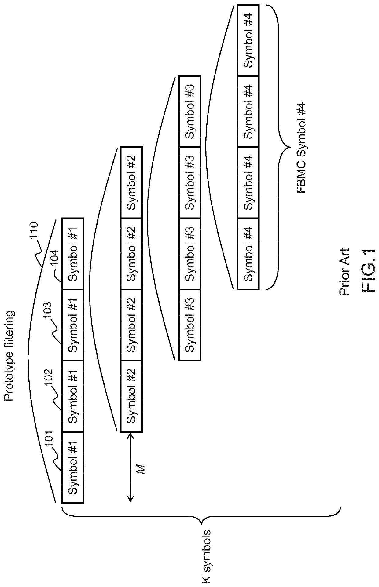
The drawback of FBMC transmission techniques lies in the absence of complex orthogonality as, at a given time, the signal transmitted is the result of the overlapping of K successive symbols combined with the effect of the filtering.
The FBMC modulation generates some inter-symbol and inter-carrier interference that introduces an additional complexity in the receiving process.
The implementation cost of an FBMC receiver corresponds mainly to the number of multipliers, and to a lesser extent the number of adders, that are required, which is of a direct impact on the size, cost, and energy consumption of the chip implementing the receiver, and is expected to be low for obvious reasons of sizing, cost, and autonomy of the receiver.
The drawback of the PPN-FBMC / OQAM receiver lies in the fact that equalization is performed after the filtering.
Indeed, in doing so, the propagation channel impulse response and the prototype filter impulse response convolute together, which makes the equalization process more complex and less efficient.
Multi-tap equalizers, that process each subcarrier to equalize along with the neighboring subcarriers using a Finite Impulse Response filter (FIR), may equally be considered as they are known to be more efficient against inter-symbol and inter-carrier interferences, but they result in a large increase of the computational load.
Its implementation cost is limited when the number of samples KM is low.
However, FBMC transmissions might show high latencies when implemented considering a long prototype filter and / or a high oversampling factor.
Indeed, the time required to demodulate and decode a symbol directly relates to these parameters, and using long prototype filters results in high transmission latencies.
However, the intrinsic robustness to multipath reflections decreases along with the length of the prototype filter, in particular when the multipath reflections show high delay spreads, which is an additional justification if required for using an equalizer at the receiver side.
In the absence of cyclic prefix (contrary to OFDM modulation), these multipath reflections introduce cyclo-stationarity issues between the FBMC symbols processed, which are minor when the prototype filter length is high but may severely impact the performances when considering short prototype filters.
Indeed, processing a FFT of a size N=PL instead of FFT 460 of a size L raises several problems, among those:the filtering must be performed over N subcarriers instead of L, which increases the implementation complexity,the subcarrier spacing is not equal to the subcarrier spacing used by the transmitter: an additional stage of down-sampling must be performed, which is not trivial when P is not an integer.
While such an implementation is compatible with the use of short prototype filters, it is rarely implemented in practice as its implementation cost is high.
Finally, another drawback of the FBMC receivers implementations known from the prior art comes from the lack of flexibility of the receiving structure to support prototype filters with various sizes in addition to overlapping factors and coefficients in a multi-user context.

Method used


Image

  • Overlap-save fbmc receiver
  • Overlap-save fbmc receiver
  • Overlap-save fbmc receiver

Examples


Embodiment Construction

[0084]The invention proposes to modify the processing of the overlap-save FBMC receiver of FIG. 5b, which can hardly be implemented in practice, in order to decrease its complexity. Classical implementations of an overlap-save receiver would consider a P ratio which value is in the order of 1.1 to 4 (depending on the delay spread of the propagation channel), the invention proposes to use a P ratio which value is integer. Indeed, while the complexity of the initial FFT shall suffer from this oversized P ratio, it makes possible to operate major simplifications of the successive computations of the receiver.

[0085]Indeed, by using a P ratio which is an integer, IFFT 530, of size N=PL, can be decomposed using a Decimation In Time method (DIT) into P IFFT of size L plus one additional stage of applying twiddle factors and summing the outputs of the P IFFTs.

[0086]FIG. 6a represents a standard IFFT, taking as inputs N=PL frequency domain samples X(0) to X(N−1), transposing these samples to...


PUM


Abstract

An FBMC equalization and demodulation unit and corresponding method to process an FBMC signal includes FBMC symbols, each FBMC symbol comprising data mapped over M subcarriers, oversampled by a factor K, filtered by a prototype filter and transposed in the time-domain, comprising: a frequency domain transposition unit, configured to transpose a block of P*KM samples comprising at least one FBMC symbol into frequency domain samples, where P is an integer greater than one, an equalizer unit configured to multiply the frequency domain samples by one or more coefficients computed from a propagation channel estimate, at least one circular convolution unit, configured to perform P circular convolutions between subsets of the equalized samples and a frequency domain response of a frequency shifted version of the prototype filter, and adders, to sum corresponding outputs of each of the P circular convolutions.

Description

FIELD OF THE INVENTION[0001]The present invention generally relates to wireless radio communications, and more specifically aims at reducing the implementation complexity of an FBMC (acronym for Filter Bank Modulation Carrier) receiver.BACKGROUND PRIOR ART[0002]Forthcoming mobile communication systems are foreseen to provide ubiquitous connectivity and seamless service delivery in all circumstances. The large number of devices and the coexistence of human-centric and machine type applications expected will lead to a large diversity of communication scenarios and characteristics. In this context, many advanced communication techniques are under investigation.[0003]Among those techniques, one is based on filter-bank multicarrier communications (FBMC) principles. FBMC transmission techniques are based on the well known Orthogonal Frequency-Division Multiplexing transmission techniques (OFDM), where the modulated symbols are mapped over different subcarriers, and transposed in the time ...

Claims


Application Information

Patent Timeline
IPC IPC(8): H04L27/26H04L25/03H04L25/02
CPCH04L27/264H04L27/265H04L25/03159H04L25/022H04L27/2698H04L27/2647H04L27/2654H04L27/26524
Inventor NADAL, JÉRÉMYABDEL NOUR, CHARBELBAGHDADI, AMER
Owner INST MINES TELECOM
Learn More