Microscopic observation system with temperature-pressure-controllable sample cell and methods

Active Publication Date: 2020-10-22
SHANDONG UNIV
0 Cites 5 Cited by

AI-Extracted Technical Summary

Problems solved by technology

However, existing international research means and characterization instruments cannot directly monitor the behaviors of materials online.
However, the microscopy cell has no temperature control function.
However, the system does not include a pressure control device, and pressure in an inner cavity of the system cannot be measured in real time.
However, the device is designed for observing fluid and is not suitable for observing a static microscopic evolution process of the polymer materials.
The inventors found that the systems and methods disclosed in the mentioned patents not only have the problem ...

Benefits of technology

[0064]Compared with a common optical microscope with a hot stage and a polarizing microscope with a hot stage, the system according to the present invention can be configured to observe the evolution process of microstructures of the polymer materials in specific atmosphere and rapid temperature and pressure changing environments. The visual system given by the present invention provides a novel characterization mea...

Abstract

A microscopic observation system with a temperature-pressure-controllable sample cell and methods. The system can be configured to perform common optical microscopic observation and polarizing microscopic observation. The system is composed of a visual autoclave, a temperature control component, a rapid cooling component, a pressure control component and an optical imaging system, and can be configured to observe an evolution process of microstructures of polymer materials in specific atmosphere and rapid temperature and pressure changing environments in a scale of 1 μm-1 cm. A novel characterization means for researching a condensed state evolution law of polymers in high-pressure environments, and also a new thought for deep reveal of the polymer crystallization mechanism and regulation of crystallization and phase separation behaviors of the polymer materials.

Application Domain

Material analysis by optical meansMicroscopes

Technology Topic

Microscopic observationMicrostructure +7

Image

  • Microscopic observation system with temperature-pressure-controllable sample cell and methods
  • Microscopic observation system with temperature-pressure-controllable sample cell and methods
  • Microscopic observation system with temperature-pressure-controllable sample cell and methods

Examples

  • Experimental program(2)

Example

Embodiment 1
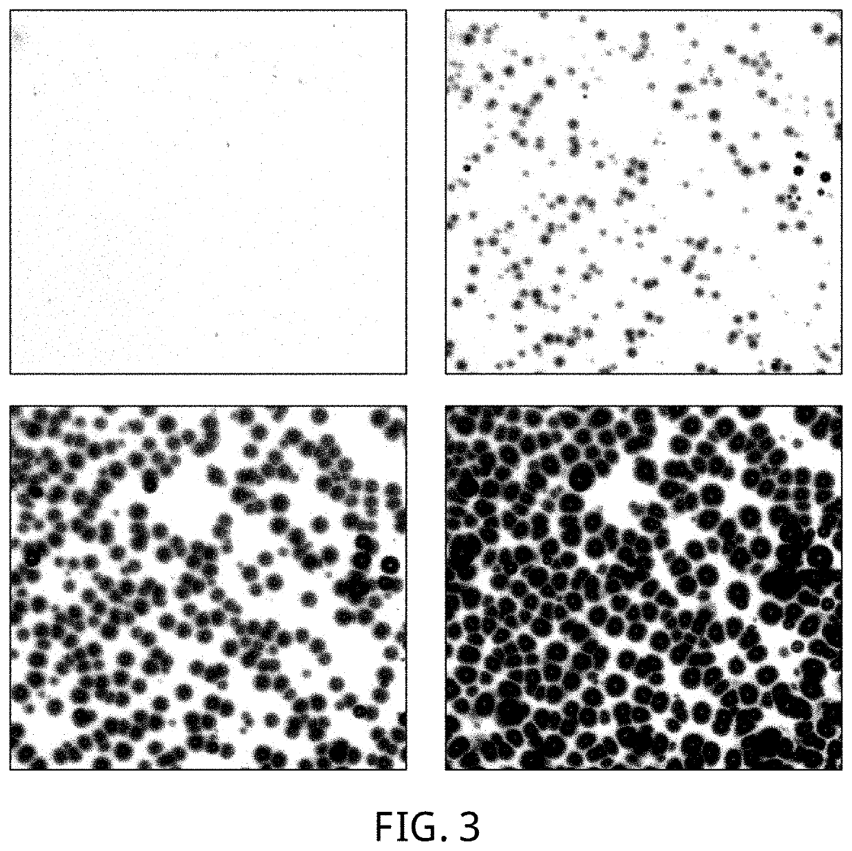
[0091]A phase separation process of a carbon dioxide/polymethyl methacrylate (PMMA) system in a rapid pressure relief process is observed by using a common optical microscopic function:
[0092]Step (1), PMMA is made into a thin sheet with a thickness being 200≈m.
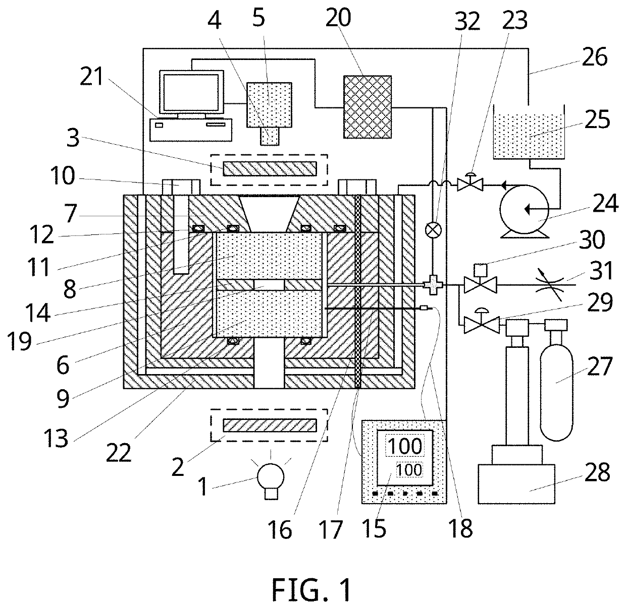
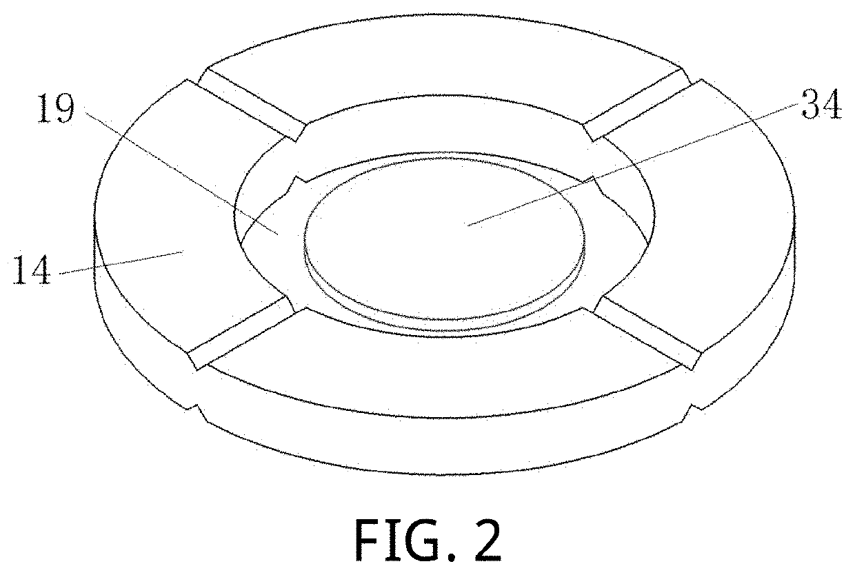
[0093]Step (2), the third sealing ring 13, the lower glass window 9 and the breathable gasket 14 are sequentially placed inside the autoclave body 6. The sample 34 is placed into central space 19 of the breathable gasket 14. Then the upper glass window 8 is placed on an upper surface of the breathable gasket 14. The first sealing ring 11 and the second sealing ring 12 are installed in a groove of the autoclave cover 7 and a groove in an upper surface of the autoclave body 6, respectively. The autoclave cover 7 and the autoclave body 6 are connected through the bolts 10 and all the parts are tightly squeezed.
[0094]Step (3), the second stop valve 29 and the third stop valve 30 are opened. The plunger pump 28 is started, and is adjusted to a constant-flow mode. Carbon dioxide is injected into the sample cell with a flow rate of 1 to 20 ml/min. Air in the autoclave is discharged.
[0095]Step (4), the temperature controller 15 is turned on. The sample cell is heated to a certain temperature higher than a glass-transition temperature of the PMMA.
[0096]Step (5), the third stop valve 30 is closed. The plunger pump 28 is adjusted to a constant-pressure mode. Carbon dioxide continues to be injected into the sample cell till a set pressure value (14 MPa for this embodiment) is reached.
[0097]Step (6), when temperature and pressure of the sample cell are stabilized at set values, timing of 1 hour is started.
[0098]Step (7), in a timing process, the amplification factor of the zoom focusing component 4 is adjusted. A central layer of the sheet sample is focused on. Intensity of the light source 1 is adjusted. Total shooting duration, exposure time and the number of shot images of the image acquisition device 5 are set to prepare to shoot.
[0099]Step (8), when timing is ended, the second stop valve 29 is closed. The image acquisition device 5 is started while the third stop valve 30 is opened, and continuous shooting or recording is started. In this process, the pressure of the sample cell changes intensely with a changing rate being about 1000 MPa/min.
[0100]Step (9), shooting is ended, and the shot images are stored as shown in FIG. 3. The temperature controller 15 is turned off, and the plunger pump 28 is shut down.
[0101]Step (10), the first stop valve 23 is opened. The liquid pump 24 is started. The sample cell is cooled with normal-temperature water.

Example

Embodiment 2
[0102]A crystallization process of poly(L-lactide) (PLLA) in high-pressure carbon dioxide is observed by adopting a polarizing microscopic function:
[0103]Step (1), PLLA is made into a thin sheet with a thickness being 15≈m.
[0104]Step (2), the third sealing ring 13, the lower glass window 9 and the breathable gasket 14 are sequentially placed inside the autoclave body. The sample 34 is placed into the central space 19 of the breathable gasket 14. Then the upper glass window 8 is placed on the upper surface of the breathable gasket 14. The first sealing ring 11 and the second sealing ring 12 are respectively installed in the groove of the autoclave cover 7 and the groove in the upper surface of the autoclave body 6. The autoclave cover 7 and the autoclave body 6 are connected through the bolts 10 and all the parts are tightly squeezed.
[0105]Step (3), the second stop valve 29 and the third stop valve 30 are opened. The plunger pump 28 is started, and is adjusted to the constant-flow mode. Carbon dioxide is injected into the sample cell with a flow rate of 1 to 20 ml/min. Air in the autoclave is discharged.
[0106]Step (4), the temperature controller 15 is turned on. The sample cell is heated to a PLLA melting point to enable the PLLA to be in a molten state.
[0107]Step (5), the third stop valve 30 is closed. The plunger pump 28 is adjusted to the constant-pressure mode. Carbon dioxide continues to be injected into the sample cell till a set pressure value is reached.
[0108]Step (6), when the temperature and pressure of the sample cell are stabilized at set values, timing of 30 min is started.
[0109]Step (7), in a timing process, the amplification factor of the zoom focusing component 4 is adjusted. A central layer of the sheet sample is focused on. The intensity of the light source 1 is adjusted. The polarizer 2 is additionally installed between the light source 1 and a light passing hole in a lower bottom of the sample cell. The analyzer 3 is additionally installed between the image acquisition device 5 and a light passing hole in an upper cover of the sample cell. The analyzer 3 is rotated until light in the view of the image acquisition device 5 is completed eliminated. Exposure time of the image acquisition device 5 is set to prepare to shoot.
[0110]Step (8), when timing is ended, a temperature setting value of the temperature controller 15 is adjusted to a PLLA crystallization temperature. The first stop valve 23 is opened and the liquid pump 24 is started simultaneously. The visual autoclave is rapidly cooled to the PLLA crystallization temperature with low-temperature cooling liquid. In this process, the temperature changes intensely with a temperature decreasing rate being about 6 éC/s.
[0111]Step (9), when the crystallization temperature is reached, timing is started. Shooting is performed and images are stored. The shot images are as shown in FIG. 4.
[0112]Step (10), after crystallization is finished, the temperature controller 15 is turned off. The plunger pump 28 is shut down. The image acquisition device 5 is turned off.
[0113]Step (11), the first stop valve 23 is opened. The liquid pump 24 is started. The sample cell is cooled to room temperature.
[0114]The specific implementations of the present invention are described above with reference to the accompanying drawings, but are not intended to limit the protection scope of the present invention. Those skilled in the art should understand that various modifications or deformations may be made without creative efforts based on the technical solutions of the present invention, and such modifications or deformations shall fall within the protection scope of the present invention.

PUM

no PUM

Description & Claims & Application Information

We can also present the details of the Description, Claims and Application information to help users get a comprehensive understanding of the technical details of the patent, such as background art, summary of invention, brief description of drawings, description of embodiments, and other original content. On the other hand, users can also determine the specific scope of protection of the technology through the list of claims; as well as understand the changes in the life cycle of the technology with the presentation of the patent timeline. Login to view more.
Why Eureka
Try Eureka