
Dynamic produced water treatment apparatus and system with oxygen recovery

a technology of produced water and apparatus, applied in the direction of waste water treatment from quaries, separation processes, well accessories, etc., can solve problems such as affecting normal operations or slowing down, and achieve the effects of reducing the hazard of explosion or fire, improving the oil/water separation process, and reducing the pressure of the injection/disposal well

Pending Publication Date: 2020-10-29
HYDROZONIX LLC
View PDF0 Cites 0 Cited by
  • Summary
  • Abstract
  • Description
  • Claims
  • Application Information

AI Technical Summary

Benefits of technology

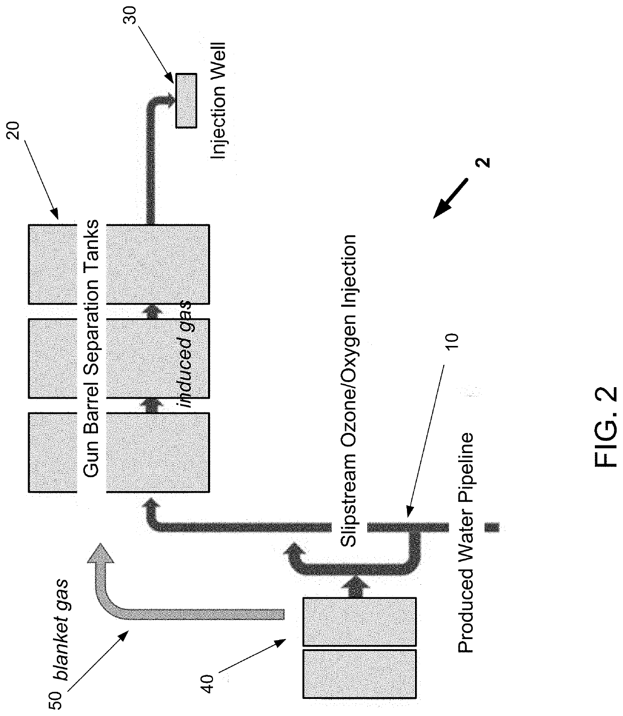
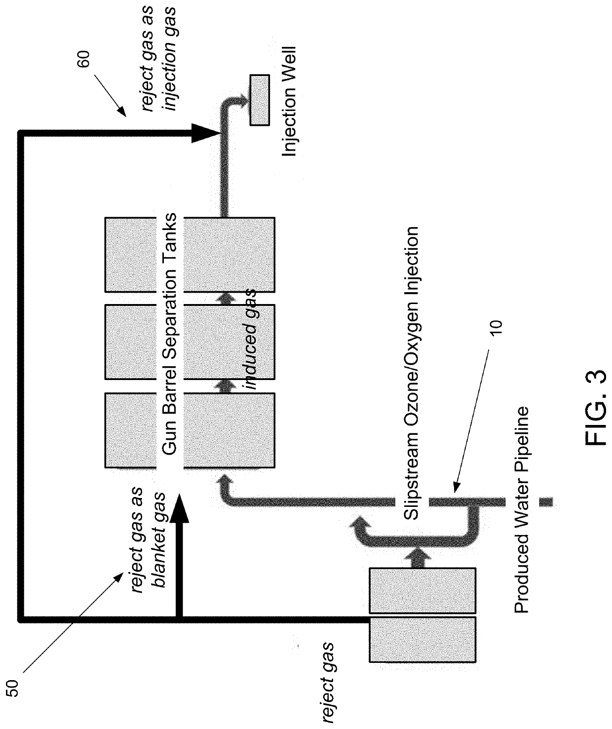
The present invention is an automated treatment system that uses ozone or ozone-oxygen mixtures to treat produced water. The system monitors the quality of the produced water in real-time and adjusts the ozone dose accordingly. The ozone reacts quickly with bacteria, iron, sulfides, and other reducers in the water stream. The oxygen bubbles in the water create a flotation effect that clarifies the water. The system can also inject other additives or disinfectants into the water. The ozone is consumed rapidly by bacteria, iron, and other contaminants, while the oxygen bubbles provide a natural flotation effect that improves the oil-water separation process. The system can also use the rejected gas from the ozone generation process as a blanket gas to protect the water from air contamination and reduce the risk of explosion or fire. The system can also reinject the oographic gas back into the pipeline in a pre-treatment or post-treatment step.

Problems solved by technology

In several embodiments, the system may operate as a “slipstream” injection system, that draws a portion of produced water from the produced water pipeline and injects ozone or an ozone-oxygen mixture back into the pipeline with disrupting or slowing normal operations.

Method used


Image

  • Dynamic produced water treatment apparatus and system with oxygen recovery
  • Dynamic produced water treatment apparatus and system with oxygen recovery
  • Dynamic produced water treatment apparatus and system with oxygen recovery

Examples


Embodiment Construction

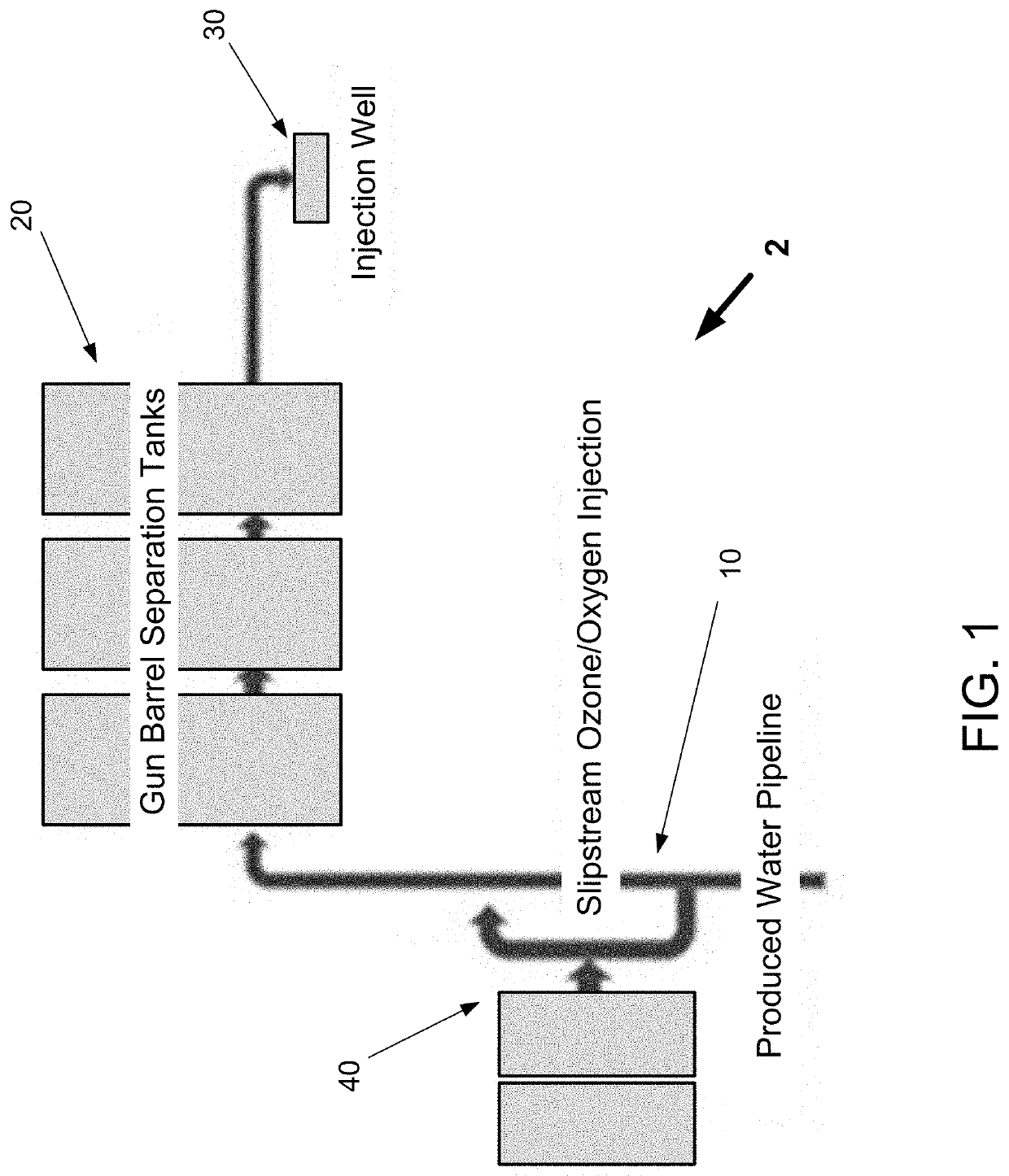
[0017]Produced water originates at the wellhead, and then typically travels via pipeline 10 to tank batteries, where held for a gathering system for processing and treatment. In general, oil or other hydrocarbons are separated and collected, and the remaining wastewater is directed to an injection or disposal well 30. One of the most common oil / water separation systems use one or more “gun barrel” separation tanks 20, as seen in FIG. 1.

[0018]As the produced water travels from the wellhead and through the gathering system, it is subjected to various treatments or processes. For example, the produced water receives injections of chemicals at or near the well head, either in batch or continuous treatments. As the produced water slows down in the gun barrel separators 20, bacteria can accumulate and hydrogen sulfide can form. To counter this, biocidal agents typically are added upstream of the gun barrel separators. Chemical biocides generally are added at a predetermined, constant dose...


PUM

PropertyMeasurementUnit
volumesaaaaaaaaaa
volatileaaaaaaaaaa
pressureaaaaaaaaaa

Abstract

An automated produced water treatment system that injects ozone or an ozone-oxygen mixture upstream of produced water separators, with the dose rate changing dynamically as the produced water quality changes, as determined by continuous monitoring of the produced water quality by a plurality of sensors that detect water quality parameters in real time. The system may operate as a “slipstream” injection system, that draws a portion of produced water from the produced water pipeline and injects ozone or an ozone-oxygen mixture back into the pipeline without disrupting or slowing normal operations. Disinfectants or other additives may also be injected. The treatment system may be wholly or partially contained in mobile containers or trailers, for on-the-fly use in existing produced water treatment facilities. An oxygen de-gasser or de-aerator may be included, configured to remove gaseous oxygen from the fluid stream

Description

[0001]This application claims benefit of and prior to U.S. Provisional Application No. 62 / 838,195, filed Apr. 24, 2019, which is incorporated herein in its entirety by specific reference for all purposes.FIELD OF INVENTION[0002]This invention relates to an apparatus and system for automatically and dynamically treated produced water from oil and gas production operations.BACKGROUND OF THE INVENTION[0003]A variety of oil and gas operations generate large volumes of water mixed with hydrocarbons and various contaminants, generally referred to in the industry as “produced water.” Most produced water is contaminated with inorganic salts, metals, organic compounds, and other materials, such as emulsifiers or other agents that may be injected for various types of enhanced recovery operations. Typical hydrocarbons in produced water include semivolatile organic compounds (“SVOCs”) and volatile organic compounds (“VOCs”). In most operations, produced water is treated by a variety of means to...

Claims


Application Information

Patent Timeline
Patent Type & Authority Applications(United States)
IPC IPC(8): C02F1/78C02F1/40C02F1/24E21B43/40
CPCC02F2101/203C02F1/24E21B43/40C02F2101/101C02F2201/782C02F2201/008C02F2103/10C02F1/78C02F2101/32E21B43/26C02F2303/04C02F1/40C02F1/20C02F2303/26C02F2209/008C02F2209/40
Inventor PATTON, MARK
Owner HYDROZONIX LLC
Learn More