Hybrid Transmission Turbojet Engine

a technology of hybrid transmission and turbine engine, which is applied in the direction of machines/engines, mechanical energy handling, mechanical equipment, etc., can solve the problem of not being able to re-inject electrical energy into the mechanical energy needed for the flight of aircraft, and achieve the effect of large gradient in quick change of the speed of the fan, and more responsive control of the devi

Active Publication Date: 2020-10-29
SAFRAN AERO BOOSTERS SA
View PDF0 Cites 7 Cited by
  • Summary
  • Abstract
  • Description
  • Claims
  • Application Information

AI Technical Summary

Benefits of technology

[0023]The turbine engine of the invention, offers innumerable possibilities for driving the fan. In particular, during certain flight manoeuvres, it may be necessary to quickly change the speed of the fan. A large gradient in the speed of the fan can usually take a long time, in particular because of the inertia of the rotating assembly. The turbine

Problems solved by technology

If this design makes it possible to transform mechanical energy into electrical energy, it is not possi

Method used


Image

  • Hybrid Transmission Turbojet Engine
  • Hybrid Transmission Turbojet Engine
  • Hybrid Transmission Turbojet Engine

Examples


first embodiment

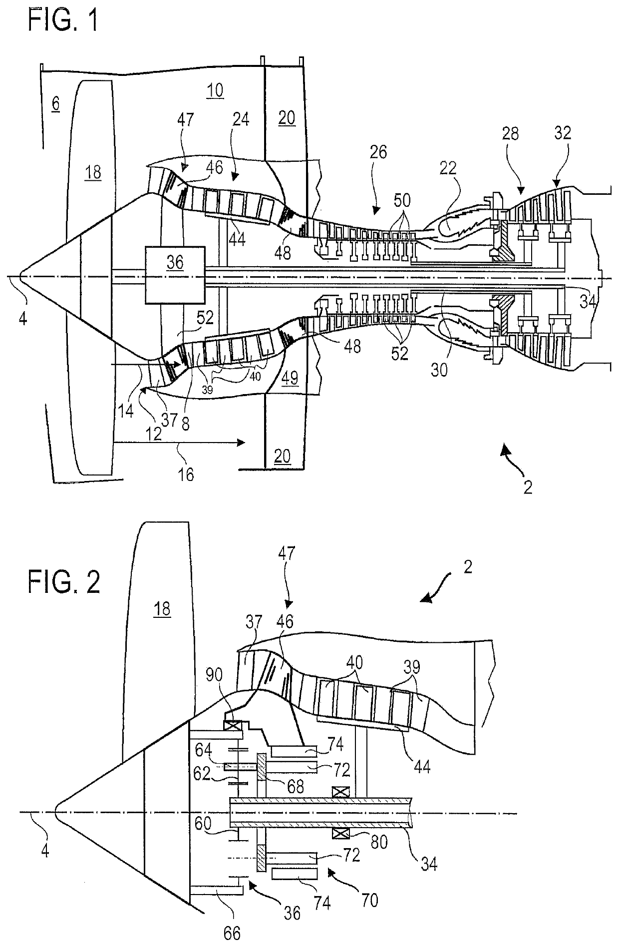
[0045]FIG. 2 illustrates an enlarged part of the turbine engine 2 of FIG. 1, with a focus on the reduction gear 36, in a The reduction gear 36 comprises a sun gear 60 secured to the transmission shaft 34. Planet gears 62 of which only one is visible in the section of FIG. 2 mesh with the sun gear 60. The planets 62 can have a double rotation movement, around their axes 64 and around axis 4. For the sake of simplicity, in this patent application we will refer to axis 64 to designate both the geometric axis of axial symmetry of a planet 62 and the physical pin or pawn, around which planet 62 revolves.

[0046]An outer ring 66 (also called the outer crown) meshes with the planets 62. In the exemplary embodiment of FIG. 2, the fan 18 fixed to the outer ring 66. The axes 64 are assembled to a planet carrier 68. Thus, when the planets 62 travel through the interplanetary space, the planet carrier 68 turns on its own axis around the axis 4. An electric motor 70 is provided to supply or recov...

second embodiment

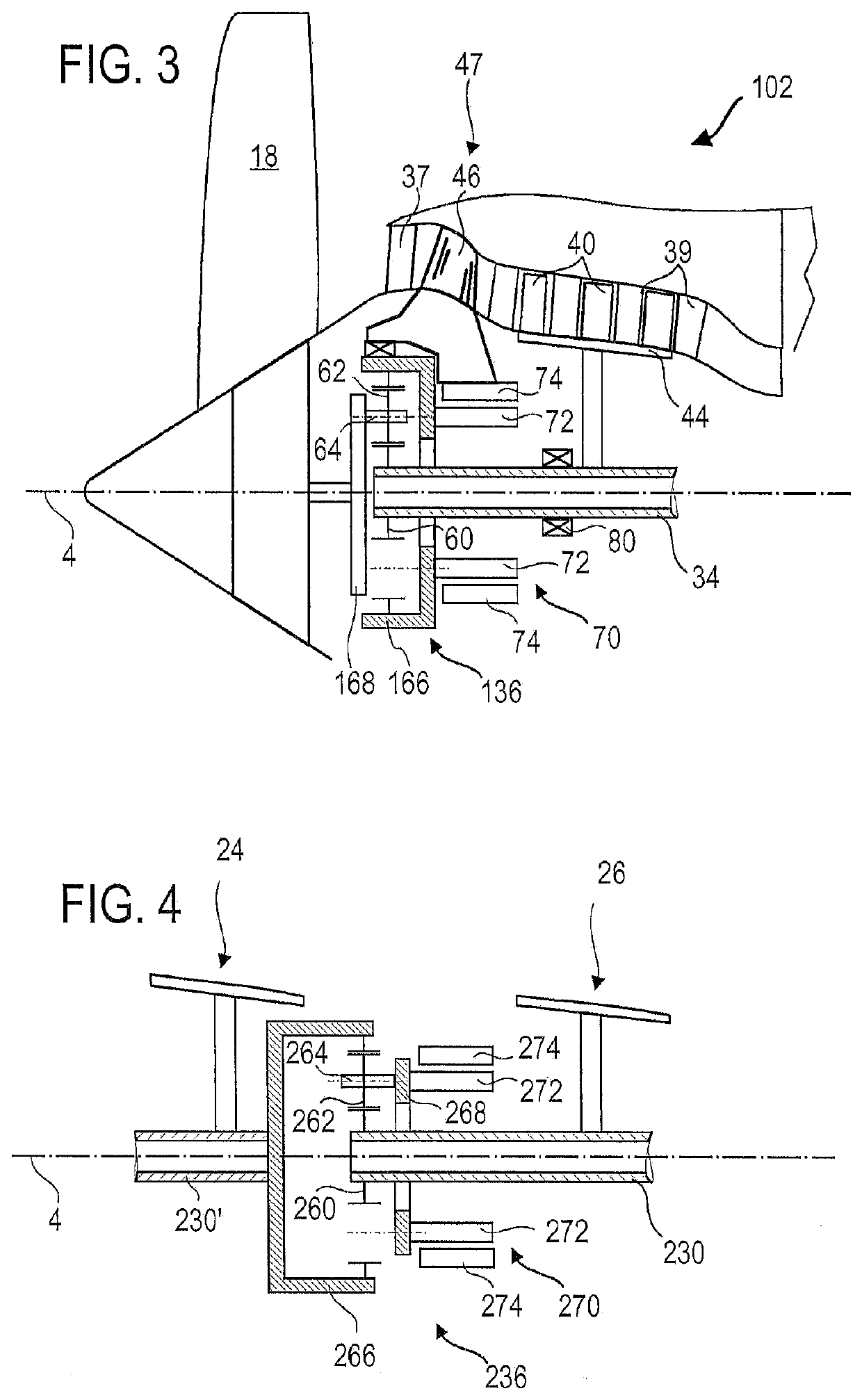
[0049]FIG. 3 represents a turbofan 102 according to the invention. Only the elements which are different from the embodiment of FIG. 2 have a referral number that is incremented by 100.

[0050]The epicyclic gear 136 is composed of a sun gear 60, planets 62 having axes 64, a planet carrier 168 and an outer ring 166. In this embodiment, the rotor 72 is integral with the outer ring 166 and the fan 18 is integral with the planet carrier 168.

[0051]The operation and the flexibility of operation of the system are identical to those of the design in FIG. 2. Only the reduction ratios are different since the fan 18 is secured to the planet carrier 168 instead of being secured to the outer ring 166.

[0052]In the two examples of FIGS. 2 and 3, the motor 70 is coaxial with the axis 4. It is however possible, depending on the available room within the turbine engine, to radially offset the rotor and therefore to connect the planet carrier 68 or the outer ring 166 to the rotor 72 by means of a belt o...

third embodiment

[0054]FIG. 4 represents part of the turbine engine 202, in a third embodiment, which can be combined with the other embodiments. In essence, an epicyclic gear 236 connects a transmission shaft 230 driven by the turbine 28 to a secondary transmission shaft 230′ which drives the fan. The secondary shaft 230′ can play the role of the shaft denoted 34 in FIGS. 2 and 3, directly, or indirectly, via a suitable reduction gear.

[0055]The low-pressure compressor 24 is driven by the secondary shaft 230′ while the high-pressure compressor 26 is driven by the shaft 230. An electric motor 270 can be provided so that its rotor 272 is secured to the planet carrier 268 of gear 236. According to an operation equivalent to that of gears 36 or 136, the electric motor 270 makes it possible to continuously regulate the speed reduction ratio between the compressors 24, 26 or to recover kinetic energy. The rotor 272 of the electric motor 270 may alternatively be integral with the outer ring 266 of the gear...


PUM


Abstract

The invention relates to a turbine engine (2), such as an aircraft turbofan engine, comprising: an epicyclic gear (36); a turbine driving in rotation a transmission shaft (34) integral in rotation with the sun gear (60) of the epicyclic gear (36); a fan (18) integral with the outer ring (66) of the epicyclic gear (36); and an electric motor (70) comprising a rotor (72) and a stator (74), the rotor (72) being integral with the planet carrier (68) of the epicyclic gear (36). Alternatively, the fan (18) is secured to the planet carrier and the electric motor (70) is secured to the outer ring.
The invention also relates to methods of using said turbofan engine, in particular for regulating the reduction ratio between the shaft and the turbine, for recovering kinetic energy or for taxiing.

Description

TECHNICAL FIELD[0001]The invention relates to the design of a turbine engine, in particular an aircraft turbofan with a fan driven by a reduction gear or an aircraft turboprop. The invention also relates to methods of using such a turbine engine.BACKGROUND ART[0002]Document US 2010 / 0326050 A1 describes a turbine engine with a compressor with counter-rotating rotors. A transmission shaft drives the fan and the first rotor lo blades (noted 17 in FIG. 2 of the document cited above). Sprockets whose axes are fixed relative to the casing ensure the transfer of rotational energy to second rotor blades (65) which rotate in the opposite direction to the first blades. An electric generator is provided, an internal rotor is integral with the first blades and an external rotor is integral with the second blades, so as to produce an electric current resulting from the rotation of the transmission shaft. If this design makes it possible to transform mechanical energy into electrical energy, it i...

Claims


Application Information

Patent Timeline
IPC IPC(8): F02C7/36F01D15/10F02C3/067H02K7/116
CPCF05D2220/36H02K7/116F01D15/10F05D2220/76F02C3/067F02C7/36F05D2220/323F05D2260/40311H02K7/1823
Inventor MALJEAN, STEPHANE
Owner SAFRAN AERO BOOSTERS SA
Why Eureka
Try Eureka