
Machine assembly, electric machine and vehicle

Pending Publication Date: 2020-11-19
ROLLS ROYCE DEUT LTD & CO KG
View PDF0 Cites 0 Cited by
  • Summary
  • Abstract
  • Description
  • Claims
  • Application Information

AI Technical Summary

Benefits of technology

This patent describes a machine assembly for electric vehicles that is cost-effective, reliable, and fail-safe. The assembly contains multiple electric machines that can easily be mechanically coupled together to provide the required power. The electric machines are designed in a similar way, making it easy to multiply their power and achieve the desired power with just a few electric machines. The presence of multiple electric machines also provides a redundant design, reducing the overall mass of the system. The rotors and stators are coupled in series, making it simple to handle and form them as a single piece. The machine assembly is compact and can fit inside a nacelle of an electric or hybrid-electric aircraft. The electric machines have high power capabilities, allowing for the assembly of powerful machines. Overall, this patent presents a cost-effective and reliable solution for powering electric vehicles.

Problems solved by technology

Furthermore, such vehicles occasionally require levels of drive power of several 100 kilowatts (kW) up to the megawatt range.
There however appears to be difficulty in further increasing the power density or the absolute power of permanent-magnet-excited motors or generators.
Furthermore, in particular in the case of aircraft with electric or hybrid-electric propulsion, the required lightweight construction imposes restrictions in terms of structural dynamics.
In some cases, these requirements are difficult to satisfy, especially as permanent-magnet-excited motors are developed individually for a specific application and power class, such that new application purposes may consume a large amount of development resources.

Method used


Image

  • Machine assembly, electric machine and vehicle
  • Machine assembly, electric machine and vehicle
  • Machine assembly, electric machine and vehicle

Examples


Embodiment Construction

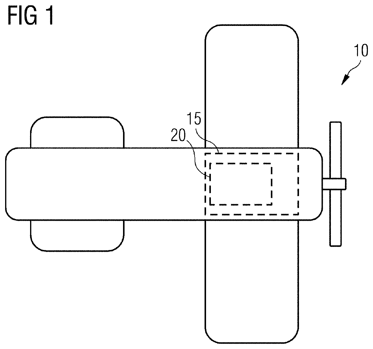
[0030]The electric aircraft 10 illustrated in FIG. 1 has a propulsion unit 15 with an electric motor assembly 20. The electric motor assembly 20 is of modular construction, as described below:

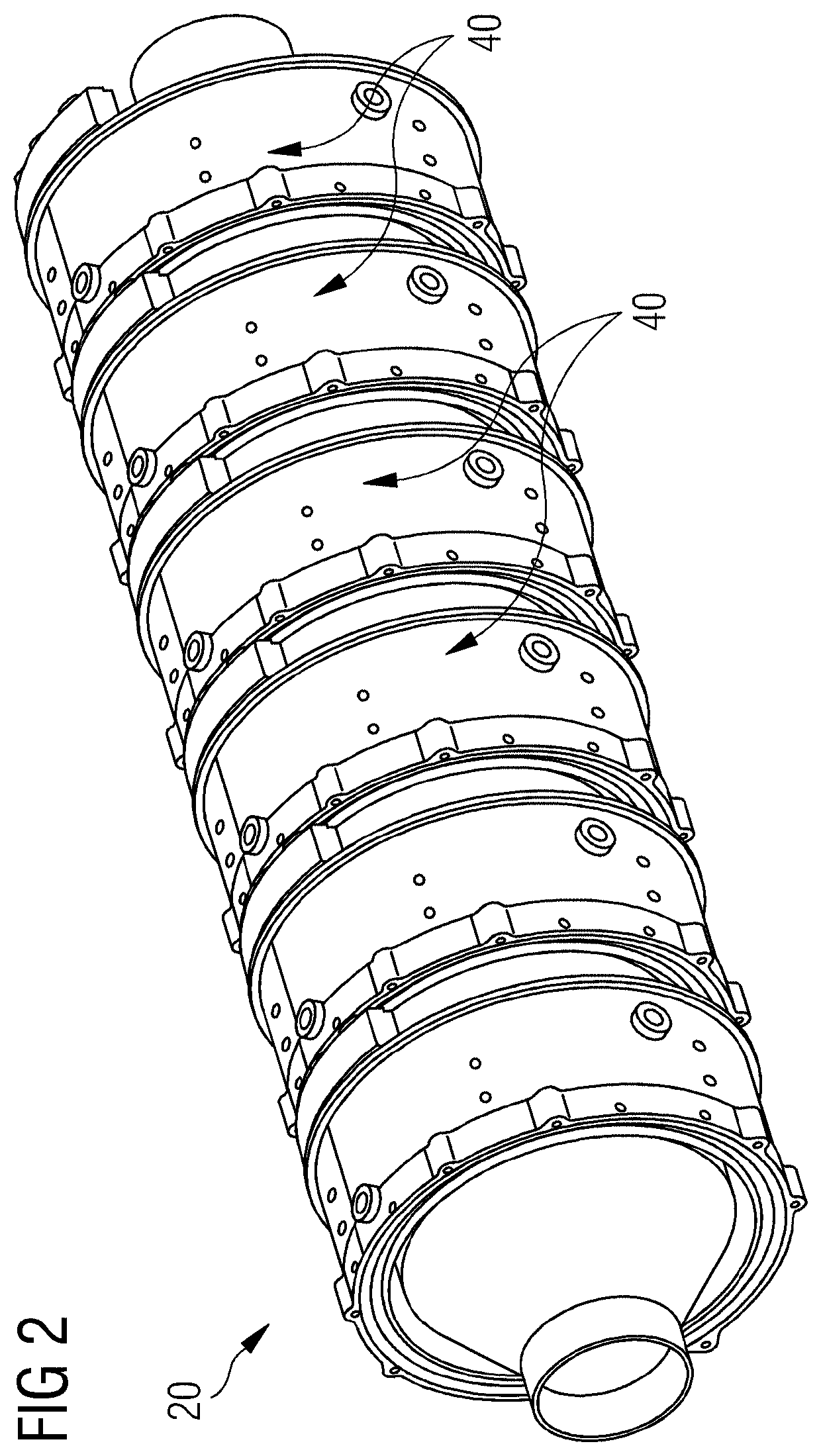
[0031]The electric motor assembly 20 is assembled from multiple, in the illustrated case six, electric motors 30, which are formed in a manner known per se with a rotor 50 which is guided, so as to be rotatable about an axis A, within a stator 40.

[0032]In the electric motor assembly 20 illustrated in FIGS. 2 and 3, both the stators 40 and the rotors 50 are mechanically coupled to one another. For this purpose, in an axial direction around which the rotors 50 are arranged so as to be rotatable, the rotors 50 are mechanically connected to one another, and the stators 40 are mechanically connected to one another, by clamping connections. The clamping connections (not explicitly shown in FIG. 2) are formed in each case by axial ends, which bear against one another, of housings 55 of the rotors 50 a...


PUM


Abstract

The machine assembly includes a plurality of electric machines, wherein rotors and / or stators of the electric machines are mechanically coupled to one another. The electric machine serves, in particular, to constitute a machine assembly and includes a housing for a rotor and / or stator, wherein the housing has a respective first and second mechanical connection element, wherein first and second mechanical connection elements correspond to one another. The vehicle may be an electric and / or hybrid-electric vehicle. The vehicle has a machine assembly and / or at least one electric machine, in particular a drive having the machine assembly or the electric machine.

Description

[0001]The present patent document is a § 371 nationalization of PCT Application Serial No. PCT / EP2019 / 052966, filed Feb. 7, 2019, designating the United States, which is hereby incorporated by reference, and this patent document also claims the benefit of German Patent Application No. 10 2018 201 985.1, filed Feb. 8, 2018, which is also hereby incorporated by reference.TECHNICAL FIELD[0002]The disclosure relates to a machine assembly, an electric machine, and to a vehicle, in particular, an electric and / or hybrid-electric aircraft.BACKGROUND[0003]Electric propulsion units of vehicles such as hybrid-electric aircraft require electric machines with a high ratio of drive power to mass (power density in relation to mass). Furthermore, such vehicles occasionally require levels of drive power of several 100 kilowatts (kW) up to the megawatt range.[0004]Permanently excited motors have the presently highest power density for electric propulsion units, wherein it is possible to attain power ...

Claims


Application Information

Patent Timeline
IPC IPC(8): H02K21/14B64D27/24
CPCB64D2027/026H02K2213/12H02K21/14B64D27/24H02K16/04Y02T10/64Y02T50/60B64D27/026
Inventor HOUSHMAND, BEHNAMLOESCH, CHRISTIANREEH, ANDREASSONS, MARKUS
Owner ROLLS ROYCE DEUT LTD & CO KG
Learn More