Eureka AIR delivers breakthrough ideas for toughest innovation challenges, trusted by R&D personnel around the world.

A method and a device for automatically determining adjustment values for operating parameters of a deposition line

Pending Publication Date: 2020-12-17
SAINT-GOBAIN GLASS FRANCE
View PDF2 Cites 3 Cited by
  • Summary
  • Abstract
  • Description
  • Claims
  • Application Information

AI Technical Summary

Benefits of technology

The invention allows for the adjustment of fabrication parameters for multiple sensitive thin layers, which would otherwise have varying characteristics due to non-adjustable parameters. By measuring the properties of the layers and adjusting the fabrication parameters accordingly, a stack of thin layers with satisfactory properties can be obtained quickly, without the need for costly and difficult to maintain in-situ instrumentation. Overall, the invention saves time and provides accurate adjustment values for the operating parameters of the deposition line.

Problems solved by technology

It can thus readily be understood that under certain circumstances (e.g. when the deposition line is of large size and has a large number of compartments), that such adjustment can be found to be complicated to implement and needs to be optimized.
That first solution can therefore turn out to be extremely lengthy and tedious to perform, even when it is automated, since it is performed individually for each layer in order to adjust the operating parameters of the deposition line.
Physically modeling a stack of thin layers is a task that is difficult, in particular when the number of layers is large and when great accuracy is expected (as applies for example when it is desired to make top-of-range products).
Such modeling requires a very large number of measurements and is extremely expensive and time consuming.
Firstly, depending on the technology used by the deposition line, it can be difficult to perform. For example, when a deposition line makes use of magnetic field assisted (magnetron) cathode sputtering, it is extremely difficult to protect the optical measurement apparatuses from interfering deposits. As a result the optical measurement apparatuses become dirtied quickly, thereby significantly degrading the measurements those apparatuses deliver and not enabling the required accuracy to be obtained for the thicknesses of the layers in the stack deposited on the transparent substrate. Furthermore, that solution requires a large number of measurement apparatuses (apparatuses need to be arranged after each compartment of the deposition line and along the entire width of the slab), and it is therefore particularly expensive and difficult to implement.

Method used


Image

  • A method and a device for automatically determining adjustment values for operating parameters of a deposition line
  • A method and a device for automatically determining adjustment values for operating parameters of a deposition line
  • A method and a device for automatically determining adjustment values for operating parameters of a deposition line

Examples


Embodiment Construction

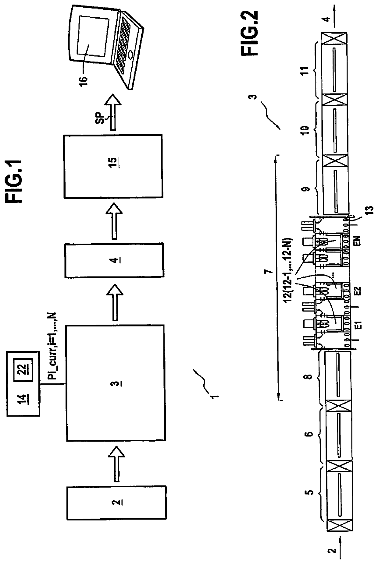
[0109]FIG. 1 shows, in its environment, a particular embodiment of a deposition system 1 in accordance with the invention for use in depositing a stack of thin layers on a transparent substrate 2 by means of a deposition line 3. The deposition system 1 serves advantageously to set the parameters of the deposition line 3 appropriately for ensuring that the stack of thin layers corresponds to predetermined target characteristics.

[0110]By way of illustration, in the example shown in FIG. 1, the transparent substrate 2 is a glass substrate having a thickness of 6 millimeters (mm) having a stack of thin layers deposited thereon, the stack comprising a plurality of functional thin layers suitable for acting on solar radiation (specifically in this example two silver layers referenced Ag1 and Ag2), and coatings formed by one or more thin layers situated on either side of each functional layer. Below, the term “module” (M1, M2, M3) is used to designate each of the coatings on either side of...


PUM

PropertyMeasurementUnit
Weightaaaaaaaaaa
Chemical propertiesaaaaaaaaaa
Widthaaaaaaaaaa

Abstract

An adjustment-determining method includes obtaining a mathematical model relating an operating parameter of the deposition line to a quality function defined from a quality measurement of a stack of thin layers deposited by the deposition line on a transparent substrate; obtaining a value of the quality function from a value of the quality measurement measured at the outlet of the deposition line on a stack of thin layers deposited by the deposition line on a substrate while the deposition line was set so that an operating parameter had a current value; and automatically determining by the mathematical model an adjustment value for the current value of the operating parameter serving to reduce a difference that exists between the value obtained for the quality function and a target value selected for the quality function for the stack of thin layers.

Description

BACKGROUND OF THE INVENTION[0001]The invention relates to fabricating transparent substrates coated on at least one face with a stack of thin layers, in particular transparent substrates made of glass or of polymeric organic material.[0002]It is conventional to provide such transparent substrates with coatings that give them particular properties, in particular optical properties, e.g. for reflecting or absorbing radiation in a given wavelength range, electrical conduction properties, or indeed properties associated with ease of cleaning or with the possibility of the substrate being self-cleaning. Such coatings are generally stacks of thin layers based on inorganic compounds, in particular on metals, oxides, nitrides, or carbides. In the meaning of the invention, the term “thin layer” is used to designate a layer of thickness that is less than one micrometer, and generally lies in the range a few tens of nanometers to a few hundreds of nanometers (whence the term “thin”).[0003]A st...

Claims


Application Information

Patent Timeline
IPC IPC(8): C23C14/34H01J37/34C23C14/35C23C14/54G05B17/02
CPCC23C14/35C23C14/3492G05B17/02H01J2237/24592C23C14/547H01J37/3464C23C14/54C23C16/52G01B11/0625
Inventor FAUCILLON, YOHANGAJIC, VOJISLAVKAUFFMANN, THIERRYSANDRE-CHARDONNAL, ETIENNE
Owner SAINT-GOBAIN GLASS FRANCE
Why Eureka
Eureka Blog
Learn More