Solder paste

a technology of solvent paste and slag, which is applied in the direction of solventing apparatus, welding/cutting media/materials, manufacturing tools, etc., can solve the problems of poor wettability, difficult to discharge voids to the outside, and easy oxidation of second alloy powder, etc., to achieve the effect of easy oxidation and poor wettability

Pending Publication Date:
View PDF8 Cites 3 Cited by
  • Summary
  • Abstract
  • Description
  • Claims
  • Application Information

AI Technical Summary

Benefits of technology

[0010]According to the invention described in Patent Document 2, the second alloy powder contains Sb and does not contain Sn in order to maintain the solid phase of the second alloy powder during reflow. Further, the document describes that the second alloy powder is uniformly dispersed in the first alloy phase while maintaining characteristics such as wettability of the first alloy phase. That is, Patent Document 2 provides that the initial form of the second alloy powder at the time of introducing is maintained, and the second alloy powder is dispersed in the first alloy phase. However, the second alloy powder can be easily oxidized due to containing Sb and has poor wettability, may not be molten into the first alloy powder which has been molten during reflow and voids are difficult to be discharged to the outside. This may result in generation of voids in a solder joint. The document also describes that an intermetallic compound phase of the first alloy powder and the second alloy powder is formed on a surface of the second alloy powder after reflow. According to the invention described in the document, only a surface of the second alloy powder is compatible with the first alloy powder, and the second alloy powder is not molten into the first alloy phase. Therefore, voids are not discharged to the outside after reflow, and voids are generated in the solder joint.
[0013]Therefore, an objective of the present invention is to provide a solder paste which suppresses generation of voids and has excellent reliability.
[0014]As described above, the solder pastes using two types of powders according to Patent Documents 2 and 3 cannot suppress generation of voids. The present inventors have studied to extract a problem related to voids by using a solder paste containing one type of solder powder containing Sb in order to secure bonding reliability. When one type of solder powder containing Sb is used, the reflow temperature should be 5 to 10° C. higher than in case of using Sn-3Ag-0.5Cu solder powder. However, since an increase in the reflow temperature imposes a thermal load on an electronic component, it is desired that the temperature is not too high. Further, since the wettability of the Sb-containing solder powder is reduced by oxidation, an increase in the reflow temperature further reduces the wettability and generates voids.
[0016]Therefore, the present inventors used an SnSb-based alloy powder including Sn in addition to Sb so as to exhibit high wettability between the first alloy powder and the second alloy powder even in case of increased Sb-content for purpose of ensuring reliability. And Sn-based powder was mixed with SnSb-based alloy powder so that the content of Sn-based powder with a low liquidus temperature and excellent wettability is larger. As a result, it was unexpectedly found that the reduction of the wettability due to the increased Sb content was suppressed, the second alloy powder melted into the first alloy phase and the generation of voids was suppressed, and the solder joint had excellent reliability.

Problems solved by technology

However, the second alloy powder can be easily oxidized due to containing Sb and has poor wettability, may not be molten into the first alloy powder which has been molten during reflow and voids are difficult to be discharged to the outside.
This may result in generation of voids in a solder joint.
Therefore, voids are not discharged to the outside after reflow, and voids are generated in the solder joint.
Thus, according to Patent Document 3, there is a problem that due to the increased viscosity of the molten solder, air confinements between the alloy powders remain inside the solder joint after reflow and voids are generated in the solder joint.
Generation of voids in the solder joint may lead to an inferior reliability for the solder joint even if the reliability of the solder alloy itself forming the solder joint is high.

Method used


Image

  • Solder paste
  • Solder paste
  • Solder paste

Examples


examples

[0055]—Preparation of Paste

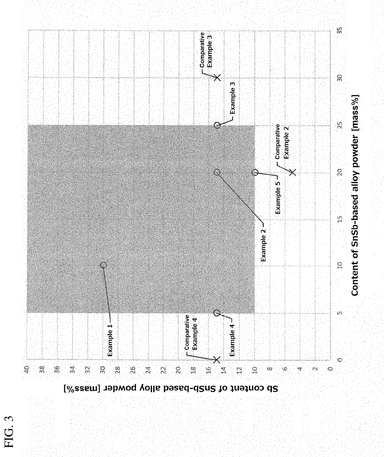
[0056]For two types or one type of alloy powder comprising alloy compositions as shown in Tables 1 to 3, an alloy powder was prepared which has a spherical diameter of 21 μm and corresponds to 5 according to the powder size classification (Table 2) of JIS Z 3284-1: 2014. The content of each powder as shown in Tables 1 to 3 represents a mass ratio (mass %) with respect to a total mass of the powders. It was then mixed with a known paste-like rosin-based flux to prepare the solder pastes of Examples 1-45 and Comparative Examples 1-4. These solder pastes had 90% of the alloy powder relative to the total mass of the solder pastes.

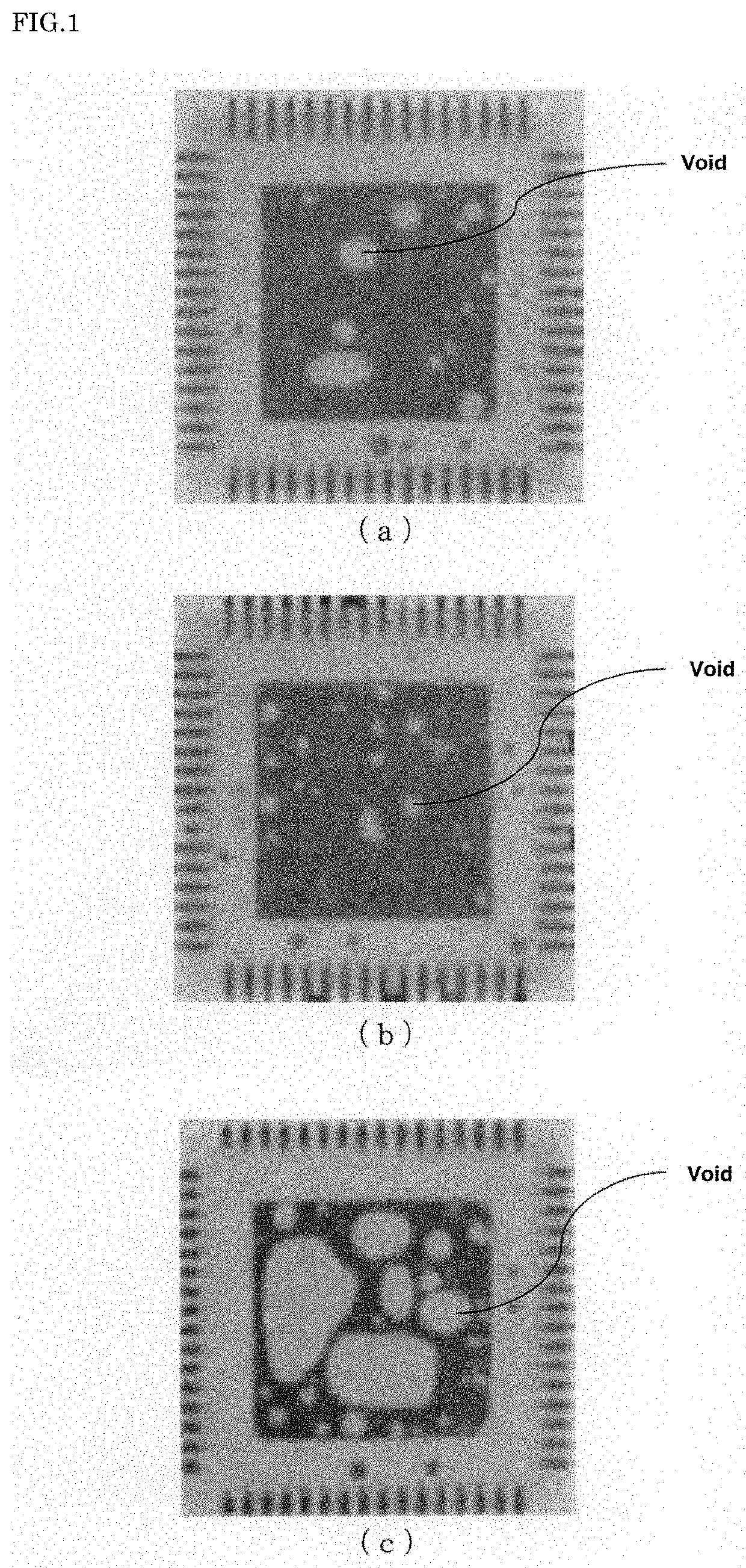
[0057]—Void Area Ratio, Maximum Void Diameter

[0058]These pastes were printed with a thickness of 0.15 mmt on a Cu—OSP glass epoxy substrate by using a metal mask. Then, by using a mounter, QFN of 8 mm×8 mm×2 mm was placed on the paste. Thereafter, it was put into a reflow furnace, and reflow heating was performed under the condition o...


PUM

PropertyMeasurementUnit
diameteraaaaaaaaaa
liquidus temperatureaaaaaaaaaa
temperatureaaaaaaaaaa

Abstract

The present invention provides a solder paste that suppresses generation of voids and has excellent reliability. A solder paste contains Sn-based powder, SnSb-based alloy powder with Sn and 10 mass % or more of Sb, and flux, wherein a liquidus temperature of the SnSb-based alloy powder is higher than a liquidus temperature of the Sn-based powder, and a content ratio of the Sn-based powder and the SnSb-based alloy powder is 75:25 to 95:5. Preferably, the content ratio of the Sn-based powder to the SnSb-based alloy powder is 80:20 to 90:10.

Description

BACKGROUND OF THE INVENTIONTechnical Field[0001]The present invention relates to a solder paste that suppresses generation of voids and has excellent reliability.Background Art[0002]In recent years, parts composed only of mechanical components for automobiles are replaced by electrical components to achieve higher functionality and higher performance of the vehicles. In order to realize higher functionality and higher performance of vehicles, electronics packaging technology is needed that is adapted for small size and high density. In order to adapt to this mounting technology, high reliability of a solder joint for connecting a printed circuit board and an electronic component is required.[0003]For example, a printed circuit board mounted near an engine is required to be used for a longtime under a considerable temperature difference. Hybrid vehicles are equipped with an inverter that handles high electric power, and require solder joints that can withstand the driving temperature...

Claims


Application Information

Patent Timeline
Patent Type & Authority Applications(United States)
IPC IPC(8): B23K35/26C22C13/02B23K35/02
CPCB23K35/0244C22C13/02B23K35/262B23K35/22B23K35/26C22C12/00C22C13/00C22C28/00
Inventor SAKAMOTO, TAKESHITACHIBANA, YOSHIEKOGA, SHUNSUKE
Why Eureka
Try Eureka