
Steel sheet and manufacturing method therefor

a technology of steel sheets and manufacturing methods, applied in the field of steel sheets, can solve the problems of inferior hole expansibility and bendability, more difficult press formability, and high probability of hydrogen embrittlement cracking, and achieve excellent chemical convertibility and plating adhesion, excellent ductility and hole expansibility, and high strength.

Active Publication Date: 2021-01-21
NIPPON STEEL CORP
View PDF3 Cites 1 Cited by
  • Summary
  • Abstract
  • Description
  • Claims
  • Application Information

AI Technical Summary

Benefits of technology

This patent text describes a way to make a strong steel sheet with good ductility and the ability to be bent without getting weaker. The method also allows for adhesive plating and chemical conversion. Additionally, the steel is resistant to fatigue and hydrogen embrittlement. The technical effect of this invention is the creation of a high-strength steel sheet that is easy to use and has improved performance characteristics.

Problems solved by technology

However, the higher the strength of the steel sheet, the more difficult the press formability.
In the case of steel sheets for vehicles, hydrogen embrittlement cracking is particularly likely to occur in a bent portion to which a large plastic strain is applied.
However, DP steel has a hard phase serving as the origin of void formation and is thus inferior in hole expansibility and bendability.
However, TRIP steel is inferior in hole expansibility.
Therefore, TRIP steel is inferior in plating adhesion and chemical convertibility.
However, it has been difficult to simultaneously improve the ductility and hole expansibility of a high strength steel sheet in the related art, and the hydrogen embrittlement resistance of a bent portion.

Method used


Image

  • Steel sheet and manufacturing method therefor
  • Steel sheet and manufacturing method therefor
  • Steel sheet and manufacturing method therefor

Examples


example

[0287]Next, examples of the present invention will be described. The conditions in the examples are one example of conditions adopted to confirm the feasibility and effects of the present invention. The present invention is not limited to this one example of conditions. The present invention can adopt various conditions as long as the object of the present invention is achieved without departing from the gist of the present invention.

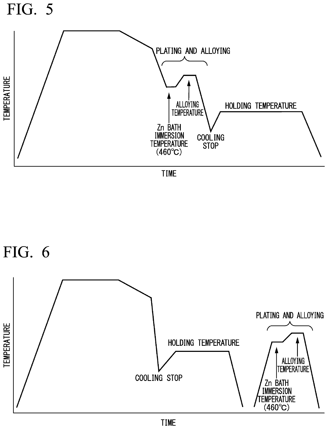
[0288]Steel having the chemical composition shown in Table 1 was melted to produce a slab. This slab was heated at the slab heating temperature shown in Tables 2 to 5 under the slab heating conditions having the numerical values of Expression (4) shown in Tables 2 to 5, and subjected to hot rolling at the temperature shown in Tables 2 to 5 as the rolling completion temperature, whereby a hot-rolled steel sheet was manufactured. Thereafter, the hot-rolled steel sheet was pickled to remove the scale on the surface. Thereafter, some of the hot-rolled steel...


PUM

PropertyMeasurementUnit
Temperatureaaaaaaaaaa

Abstract

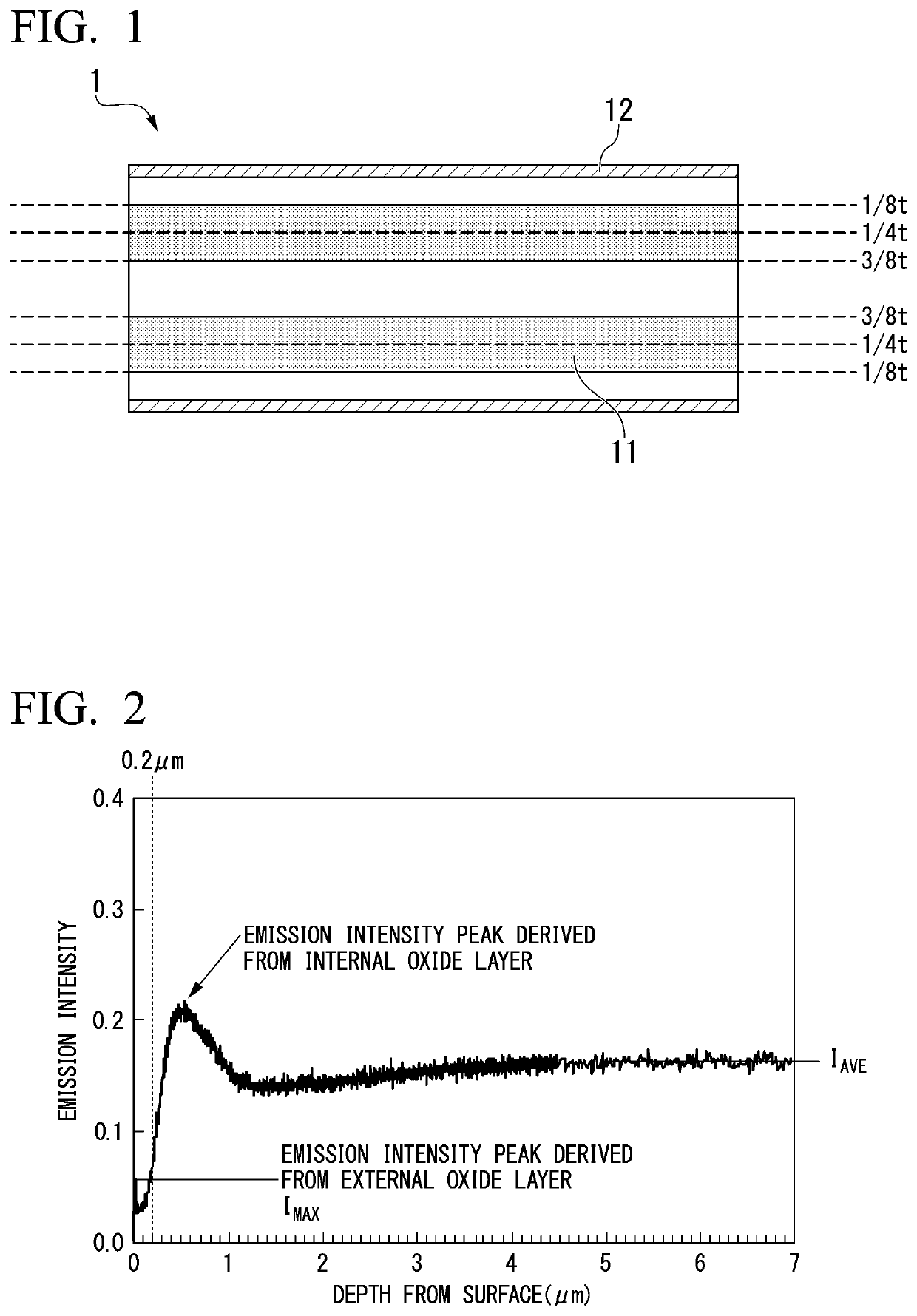
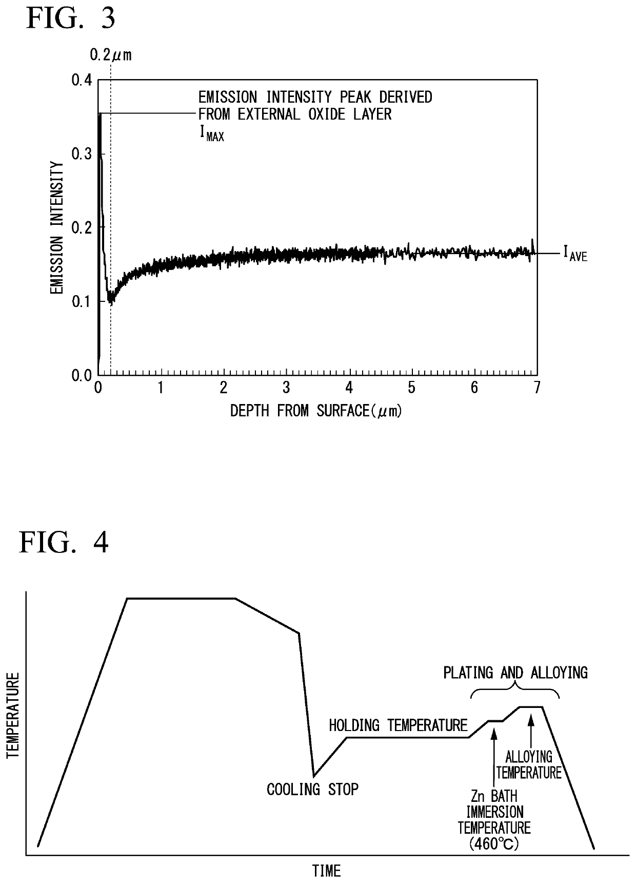
This steel sheet has a predetermined chemical composition, in which a steel structure of an inside of the steel sheet contains, by volume fraction, soft ferrite: 0% to 30%, retained austenite: 3% to 40%, fresh martensite: 0% to 30%, a sum of pearlite and cementite: 0% to 10%, and a remainder includes hard ferrite, a number proportion of the retained austenite having an aspect ratio of 2.0 or more in the total retained austenite is 50% or more, a soft layer having a thickness of 1 to 100 μm from a surface in a sheet thickness direction is present, in ferrite contained in the soft layer, a volume fraction of grains having an aspect ratio of 3.0 or more is 50% or more, a volume fraction of retained austenite in the soft layer is 80% or less of the volume fraction of the retained austenite in the inside of the steel sheet, and a peak of an emission intensity at a wavelength indicating Si appears in a range of more than 0.2 μm and 10.0 μm or less from the surface.

Description

TECHNICAL FIELD OF THE INVENTION[0001]The present invention relates to a steel sheet and a method for manufacturing the same.RELATED ART[0002]In recent years, awareness of environmental problems has increased. Therefore, in the automotive industry, it is important to reduce the weight of the vehicle body for the purpose of improving fuel efficiency. On the other hand, there is also a need to increase the vehicle body strength of a vehicle to secure collision safety. In order to achieve both a reduction in the weight of the vehicle body and collision safety, a high strength steel sheet may be used as the material of the vehicle body. However, the higher the strength of the steel sheet, the more difficult the press formability. This is because, in general, the higher the strength of the steel sheet, the lower the formability such as ductility, bendability, and hole expansibility.[0003]In the case of an ultrahigh-strength steel sheet having a tensile strength of more than 980 MPa, it i...

Claims


Application Information

Patent Timeline
IPC IPC(8): C21D9/46C21D8/02C21D6/00C23C2/06C23C2/40C22C38/18C22C38/16C22C38/14C22C38/12C22C38/10C22C38/08C22C38/06C22C38/04C22C38/02C22C38/60C22C38/00B32B15/01
CPCC21D9/46C21D2211/002C21D8/0226C21D8/0236C21D8/0263C21D6/008C21D6/005C21D6/002C21D6/001C21D6/007C23C2/06C23C2/40C22C38/18C22C38/16C22C38/14C22C38/12C22C38/10C22C38/08C22C38/06C22C38/04C22C38/02C22C38/60C22C38/005C22C38/002C22C38/001B32B15/013C21D2211/001C21D2211/005C21D2211/008C21D2211/009C21D2211/003C21D8/0205C22C38/00C23C2/02C23C2/28C21D8/0273C23C2/024C23C2/0224C22C38/58C22C38/54C22C38/52C22C38/50C22C38/48C22C38/46C22C38/44C22C38/42C21D8/0247
Inventor YOKOYAMA, TAKAFUMIOKAMOTO, RIKISANO, KOHICHIKAWATA, HIROYUKIUEDA, KOHEISAKURADA, EISAKU
Owner NIPPON STEEL CORP
Learn More