Coil arrangement for an electrical machine

a coil arrangement and electric machine technology, applied in the field of electric machines, can solve the problems of increasing the stress of electrical insulation, insulation system, and increasing the risk of system failure, so as to improve the removal of heat from the winding, increase the thermal conductivity of the impregnating compound, and ensure the effect of electrical conductivity

Pending Publication Date: 2021-02-04
ROLLS ROYCE DEUT LTD & CO KG
View PDF7 Cites 13 Cited by
  • Summary
  • Abstract
  • Description
  • Claims
  • Application Information

AI Technical Summary

Benefits of technology

[0044]In the second embodiment, that the insulating arrangement, and with it each of the various conducting and non-conducting layers, respectively, may form a surface that is closed when seen in the circumferential direction of the coil conductor around every turn of the coil formed by the coil conductor.
[0045]In the embodiments, the coil arrangement may be potted with a potting or impregnating compound. This compound may include conductive, (e.g., metallic), particles and accordingly have a certain electrical conductivity. Because, as a result of the described insulating arrangement, no electrical fields emanate any longer from the coil conductor between the individual turns of the coil and the coil conductors of adjacent coils, (e.g., different phases), in the region of the impregnation or the potting, these impregnating compounds no longer have to be of an electrically insulating design. A filling with conductive particles may hereby bring about a significant increase in the thermal conductivity of the impregnating compound, in order to improve the removal of heat from the winding.
[0046]If the first layer is grounded, neither the fillers, such as the impregnating resin, nor a possibly surrounding cooling medium has to be of an insulating design in order to prevent short circuits in the case of damage to the insulation. From the viewpoint of mechanical stability, heat conduction and protection from environmental influences, these materials do however continue to be significant in terms of insulation coordination. These properties may be improved specifically if the requirement for using insulating materials is relinquished. Consequently, for instance, specifically conductive, metallic fillers may be used to increase the thermal conductivity. Also, a cooling medium with a higher thermal capacity, such as water, may be used without increased risk.
[0047]In the electrical field-free region, the impregnating compound or else the cooling medium is not attributed any further improvement of the dielectric conditions, in particular freedom from air inclusions. As a result, much simpler application methods may be used, without compromising the lifetime of the machine.
[0048]Advantageously, the first layer, and consequently also the electrically conductive component, are grounded, so that in effect no electrical fields emanate any longer from the surface of the insulation. This obviates the need for maintaining air gaps and creep paths and for avoiding sharp edges, for example, at parts of the casing or the like, which may otherwise lead to increases of the field. There is consequently a decrease in the required design expenditure, and the installation space that correspondingly becomes free may be put to a different use, for instance, for a more compact design.
[0049]The various electrically insulating layers may be produced from a thermoplastic. Commonly used insulating materials include wire lacquers, polyimide films (e.g., Kapton), polyaramid fibers (e.g., Nomex) and corresponding laminates. Owing to a not-to-be-provided freedom from holes, poor adhesion, or lack of a flat surface, these are not ideal for a continuous, conductive coating. Furthermore, their mechanical strength is too low to allow them to be applied in the slot without a reinforcing coating. Thermoplastics, (e.g., polyether ether ketone or ‘PEEK’), on the other hand, may meet all of these requirements. Moreover, they have a high electrical dielectric strength, temperature resistance, mechanical strength, and chemical resistance. Thermoplastics may be largely freely formed or applied directly to a wire by extrusion within a continuous process. Subsequently, the desired surface regions, as aimed for here, may be provided with a metallic layer. Alternatively, by coextrusion with conductive particles, filled boundary layers may be realized in the same process act.

Problems solved by technology

With the ever-increasing performance capability of electric machines, expressed for example by the so-called power density, there is also an increase in the stressing of the electrical insulation, and consequently possibly, among other things, the risk of system failures.
In particular, as a result of operating with power electronics, the insulation system of rotating, electric machines is subjected to increased loading due to various influencing factors, (e.g., due to overshooting of the voltage provided as a result of a switching operation, due to voltage reflections at the input terminals of the machine, due to non-linear voltage drops along the winding system, and / or due to increased frequencies of partial discharges).
Such partial discharges may have such effects in the insulation system that they lead locally to an electrical short circuit, and finally to failure of the machine.
In particular, the organic insulating materials that may be used in this application area have a very low resistance to partial discharges.
There is every prospect that, in view of the current development of future generations of semiconductors, which are integrated in the power electronics ahead of the machine, this problem will continue to increase.
Although the dielectric strength for insulating materials that are used is very high, air inclusions within the insulation system represent critical weak points, where there are increases in the electrical field due to the generally lower dielectric conductivity.
As a result, even air inclusions in the range of micrometers may compromise the lifetime of such an electric machine.
However, for process-related reasons, the presence of such air inclusions cannot be completely ruled out with the commonly used impregnating processes.
An added difficulty is that, irrespective of its cause, a deterioration in the condition of the insulation may only in some cases be detected by measuring instruments.
For the conductor-conductor insulation, on the other hand, there is no established method by which the lifetime until a short-circuit occurs may be predicted or by which, in the event of a fault, it would even be possible to detect destruction of the machine in time.
However, this adaptation of the dimensioning has adverse effects on the performance of the machine.
Even this does not sufficiently solve the problem of air inclusions that remain, for example, when the preformed conductor bars are inserted into the slots of large motors or generators, because, for example, such air inclusions, and consequently the risk of partial discharges, may be caused by delamination.
Because, in effect, a prediction of interturn faults also may not be possible sufficiently reliably and with reasonable effort, the risk of partial discharges mentioned at the beginning represents a considerable safety risk.

Method used


Image

  • Coil arrangement for an electrical machine
  • Coil arrangement for an electrical machine
  • Coil arrangement for an electrical machine

Examples


first embodiment

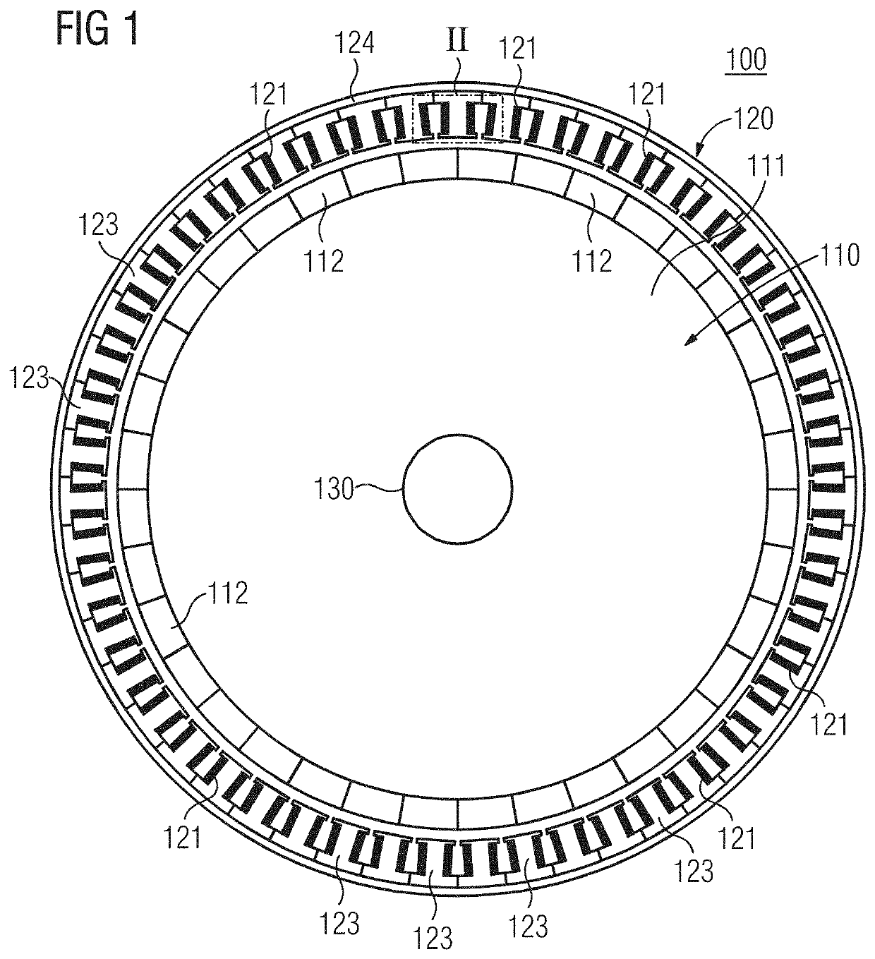
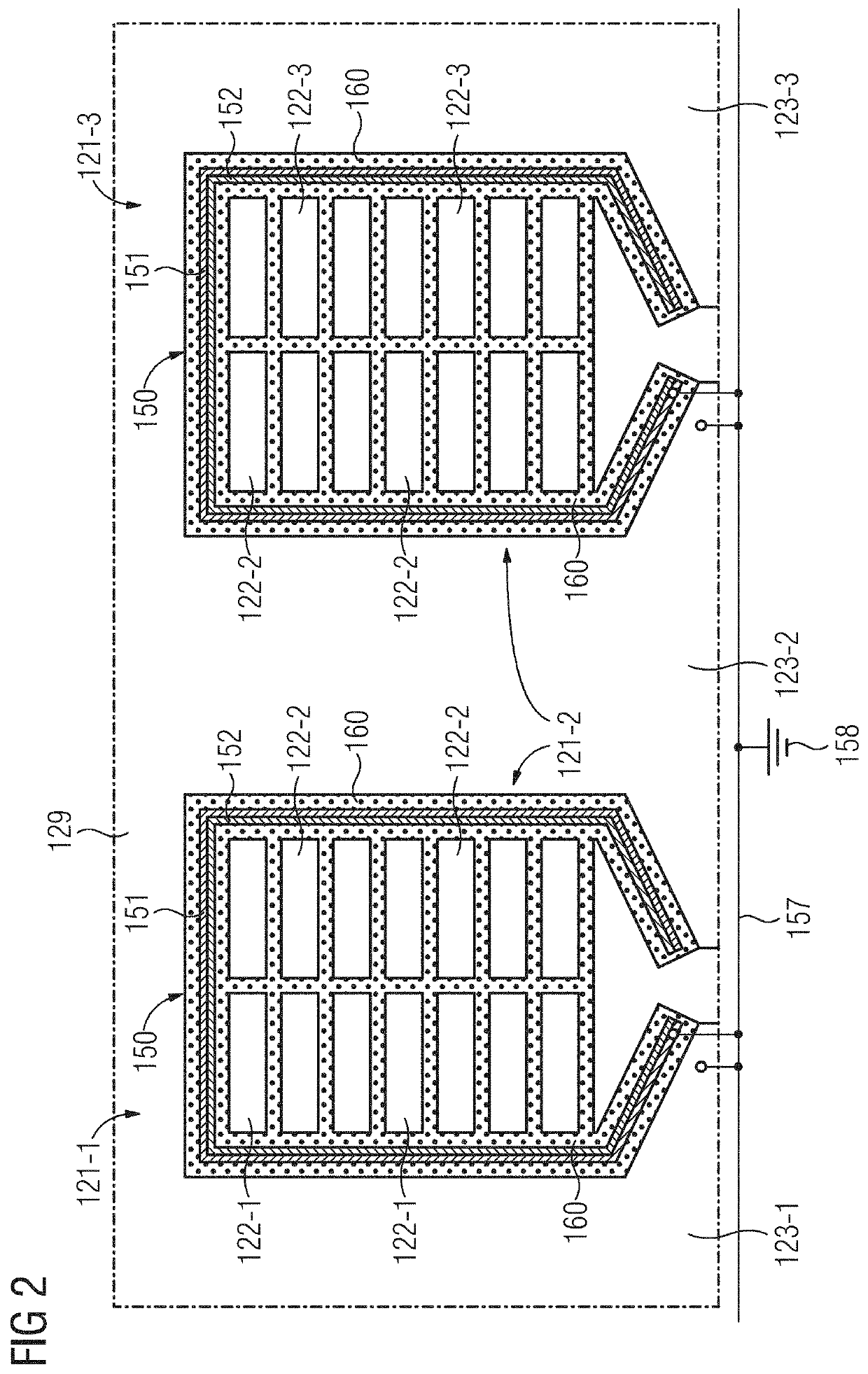
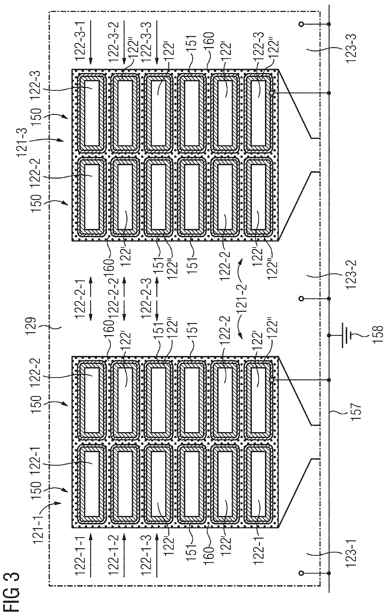
[0077]In the first embodiment, shown in FIG. 2, the insulating arrangement 150 is formed as a slot insulation. The slot insulation 150 is formed in a film-like or sheet-like manner, and therefore extends in principle, (e.g., when it has not yet been placed into the respective slot), in two spatial directions and has a comparatively negligible extent in the third spatial direction. The slot insulation 150 includes a first, electrically conductive layer 151 and a second, electrically insulating layer 152. In this example, the first layer 151, representing a conductive surface, has been applied to the second layer 152. The second layer 152 may include a thermoplastic. In this case, the slot insulation 150 is arranged in the interspace between the tooth 123-i and the coil 121-i wound onto this tooth 123-i in such a way that the first, electrically conductive layer 151 is facing the tooth 123-i and the second, electrically insulating layer 152 is facing the coil 121-i. Furthermore, the f...

third embodiment

[0084]To illustrate the functional mode, in particular of the third embodiment, FIG. 5 shows the cutout denoted in FIG. 4 by “V” and marked there by a dashed line. If the wire insulation 122″ may lift off from the wire 122′, for example, due to aging or high mechanical stressing at individual points, a local air inclusion 170 may form at the corresponding point. Because the further layer 155 is arranged completely surrounding the wire 122′, the electrical contact between the wire 122′ and the further layer 155 remains ensured, so that the function of the insulating arrangement 150 with regard to the avoidance of partial discharges is also ensured in this case. In other words, the occurrence of partial discharges due to delamination of the wire insulation 122″ from the wire 122′ may therefore be additionally prevented by the additional conductive surface in the form of the further layer 155 between the wire insulation 122″ and the wire 122′.

[0085]FIG. 6 shows a fourth embodiment of t...

fourth embodiment

[0087]In the third and also in the fourth embodiment, which are shown in FIGS. 4-6, the insulating arrangement 150 in each case includes an electrically insulating layer 122″ or 152, respectively. On both sides of this insulating layer 122″ or 152 there is arranged in each case an electrically conductive layer 151, 155 or 151, 153, respectively. By such an electrically conductive coating on both sides of the insulating layer 122″ or 152, both the region between the insulation 122″ or 152 and the laminated core 129, and that between the insulating arrangement 150 and the coil conductor 122 is kept free from partial discharges.

[0088]For the production or the construction of the stator 120 on the basis of one of the second to fourth embodiments, the coil conductor 122 insulated in this way may be pre-formed and inserted into the slot or be wound directly onto the tooth 123. As a result, the electrically conductive first layer 151 located on the respective outer side of the coil conduct...


PUM


Abstract

The disclosure relates to an electric machine of an electrical system, (e.g., a drive system), and in particular to the electrical insulation of a coil of the machine. A coil arrangement includes a coil, formed by an electrical coil conductor, and also an insulating arrangement. The coil is arranged at an electrically conductive element of the machine, for example, at or on a corresponding tooth of a stator or of a rotor of the machine, which is formed by a laminated core. The insulating arrangement is configured to insulate the coil from the electrically conductive element, (e.g., from the laminated core forming the tooth). The insulating arrangement has a first, electrically conductive layer, which is at least partly arranged between the coil and the metallic component. Furthermore, the first layer is electrically connected to the metallic component, in order to prevent partial discharges between the insulating arrangement and the metallic component.

Description

[0001]The present patent document claims the benefit of German Patent Application No. 10 2019 211 267.6, filed Jul. 30, 2019, which is hereby incorporated by reference.TECHNICAL FIELD[0002]The disclosure relates to an electric machine of an electrical system, (for example, of an electrical drive system), and in particular to the electrical insulation of the winding system of the machine.BACKGROUND[0003]With the ever-increasing performance capability of electric machines, expressed for example by the so-called power density, there is also an increase in the stressing of the electrical insulation, and consequently possibly, among other things, the risk of system failures. In particular, for the case where the machine is to be used in a safety-critical environment, (e.g., as a component of a drive system of an electrically powered aircraft), an extremely high degree of failure safety is targeted. The electrical insulation system of the machine in particular plays a significant part her...

Claims


Application Information

Patent Timeline
Patent Type & Authority Applications(United States)
IPC IPC(8): H02K3/34H02K3/12H02K15/10
CPCH02K3/345H02K15/105H02K3/12H02K3/34H02K3/30
Inventor SCHULZ, FLORIAN
Owner ROLLS ROYCE DEUT LTD & CO KG
Why Eureka
Try Eureka