Vacuum transfer assembly

a vacuum transfer and assembly technology, applied in the field of vacuum transfer assembly, can solve the problems of affecting the cost of use is typically high, and the pumping time is typically several hours, so as to achieve good vacuum, improve the cooling effect of cryo samples, and facilitate the maintenance of a very low vacuum

Pending Publication Date: 2021-02-25
HENNYZ BV
View PDF0 Cites 2 Cited by
  • Summary
  • Abstract
  • Description
  • Claims
  • Application Information

AI Technical Summary

Benefits of technology

The present invention is a microscope sample holder with an ultra-high vacuum system. The technical effects of the invention include the ability to have a vacuum in the microscope, which requires a separate pumping system and a vacuum tightness between the tip and the sample holder. The pumping system can create a vacuum around the outer end of the sample holder by using a hood on the receiving rod. The sample holder is much less sensitive to vibrations, allowing for better resolution and the use of heavier sample holders without degrading the resolution. The sample holder is also wider, allowing for more sample movements. The invention does not have a secondary airlock in the goniometer, which allows for better mechanical stability and a better image resolution. The vacuum housing is designed for easy sliding of the sample holder in and out, and the sample stage can have better stability and drift stabilization. The vacuum housing and sample holder are adapted to provide sliding of the sample holder into and out of the vacuum housing.

Problems solved by technology

Prior art systems in which a complete cryotransfer system integrated in a dedicated TEM with a sample holder permanently fitted into a side entry are used are typically expensive and do not allow any in-situ experiments whereas specific cryotransfer holders that can be inserted into the side entry of other TEMs are very user-unfriendly and still allow for specimen degradation due to ice formation on the sample.
This pumping takes typically several hours.
The valve is small to keep the weight of the holder within an acceptable limit, and therefore the pumping speed being limited by the valve size is low as well.
The sealed area is small given the maximum dimensions of the holder and there is no space for a sensor to measure the effectiveness of the airtight seal and thus one cannot measure the gas conditions to which the sample has been exposed.
Moreover, opening the sealed area in the TEM is not an option, since this will deteriorate the vacuum of the TEM too much and opening the sealed area in the airlock will result in a much higher partial pressure of for instance water and oxygen.
It is noted that the side-entry goniometer of prior art TEMs is a very fragile and very complex, whereas it is one of the most essential components of a TEM.
The insertion through air has a number of disadvantages: a) poor vacuum in the TEM, b) no air sensitive samples can be inserted easily, c) cryotransfer of cryosamples is complicated and always ice formation on the tip of the holder will occur.
A further disadvantage of the prior art goniometer is that a small change (−4 Pascal or less).
The microscope operator can make mistakes during insertion of the holder and the rotation at a certain point of insertion to open the valve, which mistakes can lead to breakage of the vacuum of the TEM or mechanical damage of the holder or the goniometer.
Furthermore the rotation of the holder, needed to open the valve in the goniometer, can lead to accidental loss of components (like the sample falling out), which could accidently not be fixed well in the holder, from the sample holder into the goniometer.
This ice has to be pumped away once the sample holder is in the TEM vacuum, resulting in a poor TEM vacuum until all ice / water is removed.
This has the disadvantage that the rod on which the sample is placed has a small diameter, since it has to fit inside the second airlock, and as further disadvantage that the second airlock adds a substantial length to the goniometer / holder combination, which may result in resolution loss.
The small diameter of the rod on which the sample is placed limits the possibilities of sample cooling and adding in-situ stimuli like biasing tools severely.

Method used


Image

  • Vacuum transfer assembly
  • Vacuum transfer assembly
  • Vacuum transfer assembly

Examples


examples

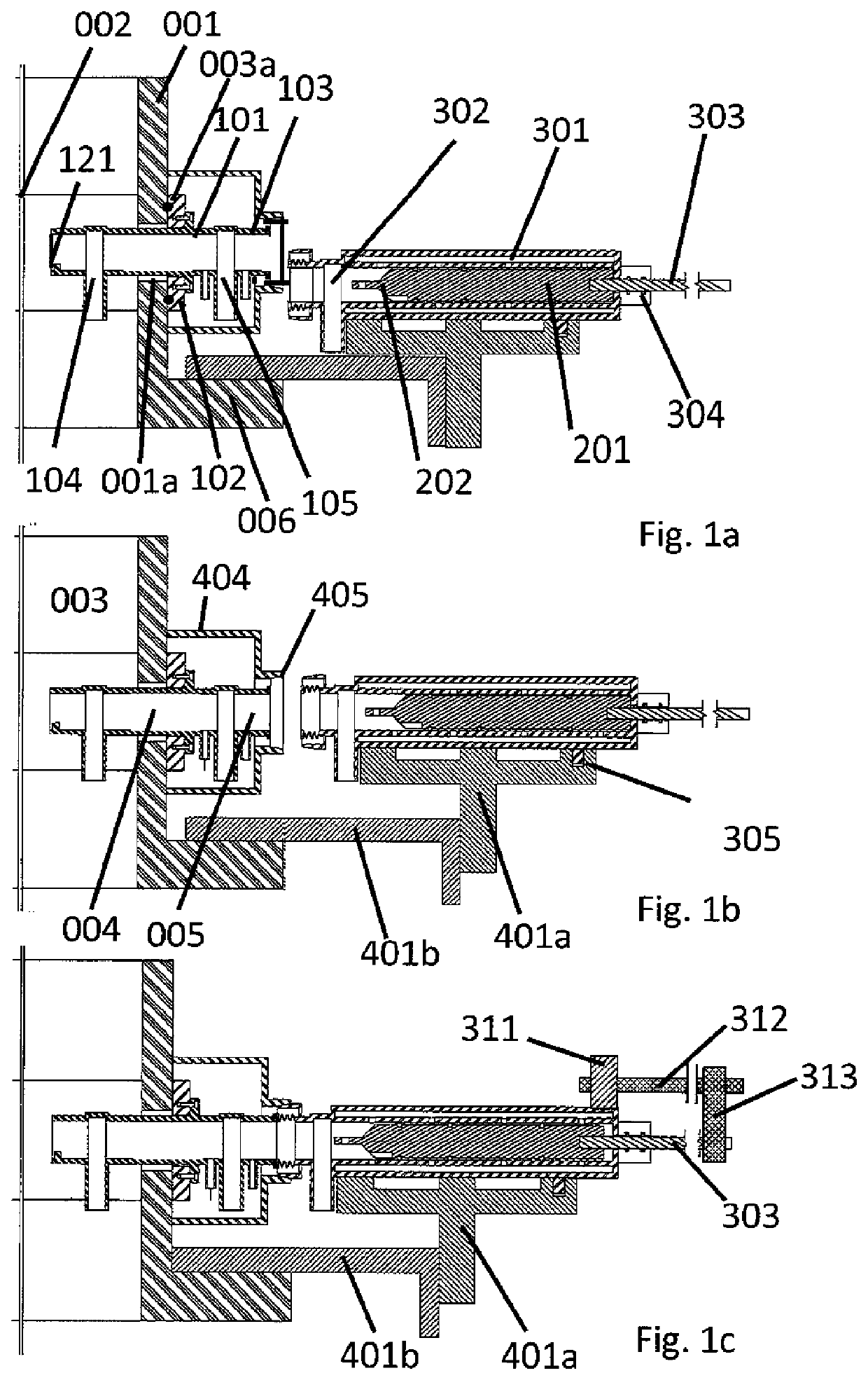
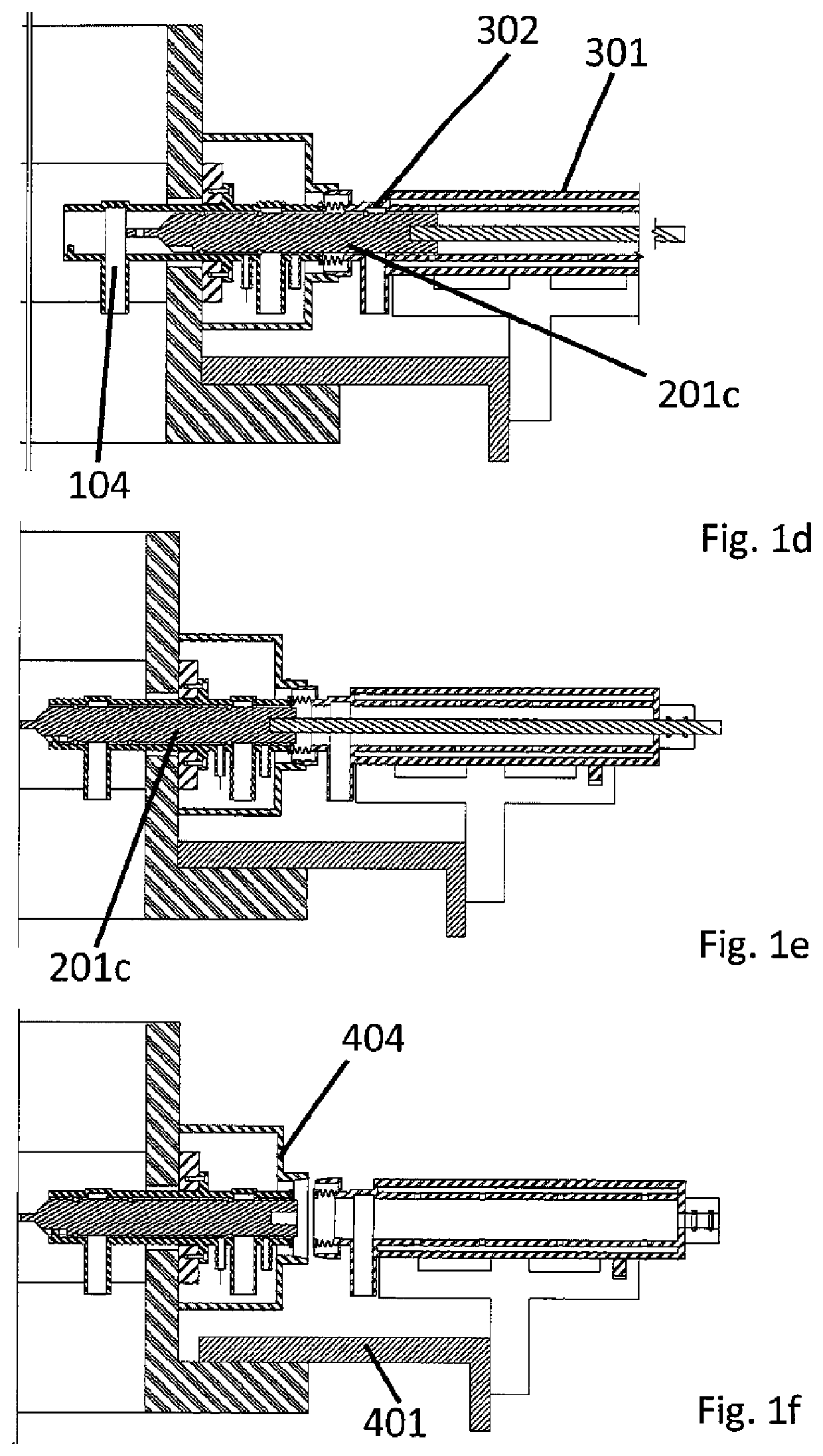
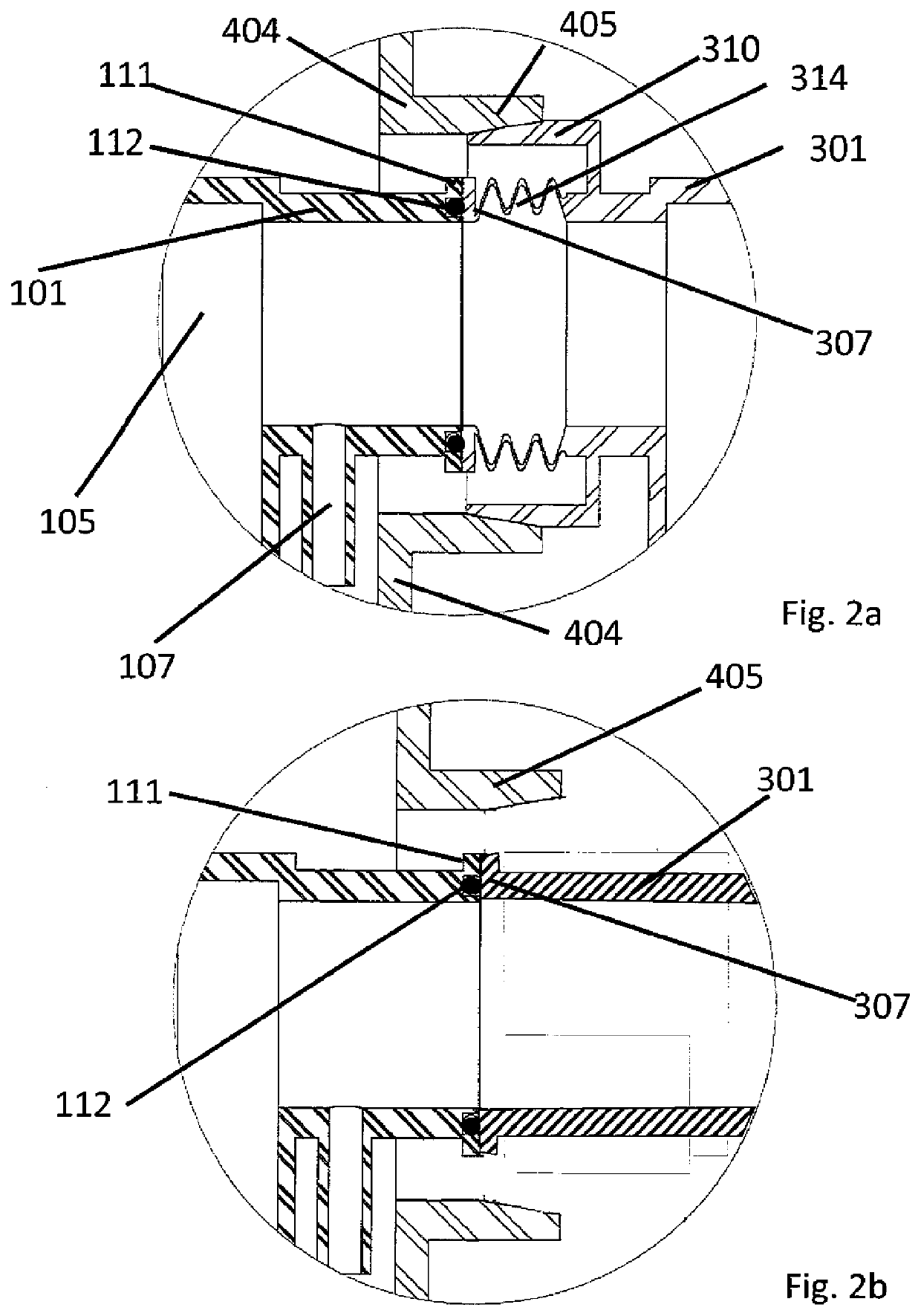
[0052]Exemplary Workflow for Vacuum Transfer[0053]1. Set the 401 coupling unit and the sample holder stage 101 in the receive-position.[0054]2. Load the sample in the tip of the sample holder 201 that is located in a glove box 901.[0055]3. Draw back the sample holder fully into the vacuum housing 301.[0056]4. Close the valve of the glove box and the valve 302 of the vacuum housing (pressure within vacuum housing is still at about 1 bar with e.g. Ar; alternatively the vacuum housing can be evacuated through tube 913 before closing the valve on the vacuum housing).[0057]5. Decouple the vacuum housing (with the sample holder in it) from the glove box.[0058]6. Place the vacuum housing (with the sample holder in it) on the coupling unit and clamp the two together.[0059]7. Move the vacuum housing with the coupling unit such that the vacuum housing is fully aligned with the sample holder stage with a separation distance of e.g. 2 mm.[0060]8. Activate the electromagnet to make a connection ...


PUM


Abstract

The present invention is in the field of a vacuum transfer assembly, such as for cryotransfer, and specifically a TEM vacuum transfer assembly, which can be used in microscopy, a sample holder, a vacuum housing, a sample holder stage and a sample holder coupling unit for use in the assembly, and a microscope comprising said assembly as well as a method of vacuum transfer into a microscope.

Description

FIELD OF THE INVENTION[0001]The present invention is in the field of a vacuum transfer assembly, such as for cryotransfer, and specifically a TEM vacuum transfer assembly, which can be used in microscopy, a sample holder, a vacuum housing, a sample holder stage and a sample holder coupling unit for use in the assembly, and a microscope comprising said assembly as well as a method of vacuum transfer into a microscope.BACKGROUND OF THE INVENTION[0002]The present invention is in the field of microscopy, specifically in the field of electron and focused ion beam microscopy (EM and FIB), and in particular Transmission Electron Microscopy (TEM). However its application is extendable in principle to any field of microscopy, especially wherein a specimen (or sample) is cooled or needs cooling, or has to be protected from air.[0003]Microscopy is a technique often used in scientific research. It is widely used in life sciences and materials sciences to obtain information in the 0.1 nm to 1 μm...

Claims


Application Information

Patent Timeline
IPC IPC(8): G02B21/32H01J37/20
CPCG02B21/32H01J37/20H01J2237/2802H01J2237/2004H01J2237/204H01J2237/2001
Inventor ZANDBERGEN, HENDRIK WILLEM
Owner HENNYZ BV
Why Eureka
Try Eureka