Passive tailings compactor

a tailings compactor and tailing technology, applied in the direction of separation processes, geotextiles, chemistry apparatus and processes, etc., can solve the problems of further reducing geotechnical stability and strength, low hydraulic conductivity, and poor geotechnical strength parameters, so as to achieve high hydraulic conductivity and reduce labor costs , the effect of high conductivity

Inactive Publication Date: 2021-03-04
PATRICK BROWN TECH INC
View PDF0 Cites 0 Cited by
  • Summary
  • Abstract
  • Description
  • Claims
  • Application Information

AI Technical Summary

Benefits of technology

[0011]The invention is described as a passive tailings compactor. This invention provides a low-cost, low-energy solution to the challenge of continuously removing excess interstitial water from fine-grained sedimentary materials in an active deposition environment. The invention allows for the accelerated compaction of fine grained materials by providing vertically-oriented drainage conduits of relatively higher hydraulic conductivity within a mass of fine-grained sediments. These conduits allow for gravitational forces to compact the sediments by causing the heavier mineral particles to displace interstitial water into the drainage conduits, where the water is transported to an area of lower pressure (typically upwards toward the supernatant pond or surface). The drainage conduits are positioned as a part of a network of many passive tailings compactor systems which are spaced depending upon the hydrological properties of the material being drained, deposition rate, and the desired speed of consolidation. This network of conduits serves to effectively increase the bulk hydraulic conductivity of the material being drained which allows it to consolidate more rapidly than possible in its untreated state.
[0012]The invention is a system comprised of three primary components: a bottom anchor mass; a flotation device which serves to anchor the system horizontally from the top while controlling the vertical extension of the system upwards; and a drainage conduit which connects from the bottom anchor to the top flotation device. The flotation device is also used to store drainage conduit required for future vertical extensions of the sediment basin. This conduit is wrapped around a central axis on the flotation device (effectively a spool). The flotation device is rounded to facilitate low-friction rotation around its axis when sitting on top of either water or sediments, allowing it to release additional drainage conduit as the depth of the sediment or water basin increases. This rotation is further controlled by asymmetrically weighting the flotation device to create an effective moment arm around the rotational axis when upsetting rotational forces are applied (such as wind shear or tension on the drainage conduit caused by increases in pond elevation lifting the flotation device). This increases the magnitude of the rotational force required to cause the device to rotate around its axis, helping to prevent the un-intended release of drainage conduit from the spool due to reasons other than an increase in the elevation of flotation device (such as the wind). The positive relative buoyancy of the flotation device compared to either water or mineral sediments generates a large upward force on the device when pond or sediment elevations increase as a result of sediment deposition, and due to the connection of the drainage conduit from the flotation device to the bottom anchor, the device is caused to rotate around its axis, releasing additional conduit and extending the vertical height of the system upwards. In this manner the device can extend upwards until drainage conduit is exhausted. At that point, additional drainage conduit can be connected into the system using a splice, and the vertical extension range is increased. Alternatively the flotation devices can be removed when drainage conduit length is exhausted, or simply left in place and buried or submerged by increasing sediment / pond elevations if desired. This is likely to be the case when a sediment storage facility (tailings pond) nears the end of its operational life and is prepared for closure.
[0013]The invention is novel due to its ability to function continuously in its purpose of providing drainage pathways through thick layers of sediments which have been and continue to be continuously deposited around the system in place. It achieves this purpose through its ability to extend vertically in tandem with the water / sediment level in the basin as the basin increases in vertical depth, all while continuing to provide un-broken drainage conduits through the entire vertical section of sediments. This invention allows all levels of sediments (deep through to shallow) to continuously drain and consolidate by connecting them hydraulically through a vertical conduit of relatively high hydraulic conductivity to the surface or a supernatant pond (providing a pathway of release) without interrupting the continued operation of further sediment deposition.
[0014]The invention can be installed either prior to deposition in a new facility, or in an active deposition environment from boats, amphibious machines, or helicopters depending on the characteristics and accessibility the containment facility in question. Installing the system requires only for the system to be dropped into the desired location in such a manner that the flotation device is free to rotate, releasing drainage conduit as the anchor sinks and / or the pond level rises over time. Installation is rapid and can be achieved with minimal cost in labour and specialized equipment (most facilities can effectively use small boats). Subsequent to installation, during the course of continuing operations of the sediment storage facility (tailings pond), the network of passive tailings compactors should not require additional modification, energy input, or adjustment, and as such do not present risks and costs associated with repeatedly accessing the interior of the sediment impoundment facility, which can be significant. This invention solves these logistical challenges while providing all the benefits and more of conventional sediment drainage technologies by way of its continuous operation: typical drainage technologies are installed once and treat previously-deposited sediments only, providing no benefit in terms of dewatering subsequently deposited materials.

Problems solved by technology

Fine-grained materials with high water contents often demonstrate low hydraulic conductivities and poor geotechnical strength parameters.
Low hydraulic conductivity also impacts the geotechnical properties of the material when external forces are applied and interstitial water becomes pressurized.
This typically results in a further reduction in geotechnical stability and strength (examples of such external forces are construction loads or seismic loads).
The pressurization of pore water can result under certain circumstances in the liquefaction of a material occurring, with a resulting catastrophic loss in material strength.
Fine-grained sediments created by the mineral processing (mining) and other industrial sectors often are generated at a high volumetric rate which is not conducive to large-scale dewatering from an economic standpoint.
The materials are frequently transported via hydraulic means in pipes prior to deposition, resulting in high moisture contents.
Due to the low hydraulic conductivities and fine particle sizes often exhibited by these materials, settlement and dewatering is often very slow and cannot effectively occur before the material is trapped beneath subsequent layers of deposition (these problems are further exacerbated by material grain size segregation occurring within storage facilities).
Waste storage facilities during operation typically have very poor surface stability conditions unsuitable for most heavy equipment or personnel access.
Downward-installed drains require either stable working surfaces or complex platform / barge systems which are generally either highly expensive or impractical during operating periods.
Subsequent to deposition periods, downward installed wick drains provide less economic incentive to invest, as the facility is no longer operating and generating revenue.
Downward-drilled wick drains also only impact the dewatering of existing sediments, as the discharge points of the drains would be quickly buried in typical mineral processing environments, causing them to cease functioning, and providing no benefits for the dewatering of subsequently-deposited sediments.
These processes are energy and infrastructure intensive, with complex logistical challenges and as such have only infrequently and in specific circumstances been adopted by large-scale mineral processing operations.

Method used


Image

  • Passive tailings compactor
  • Passive tailings compactor
  • Passive tailings compactor

Examples


Embodiment Construction

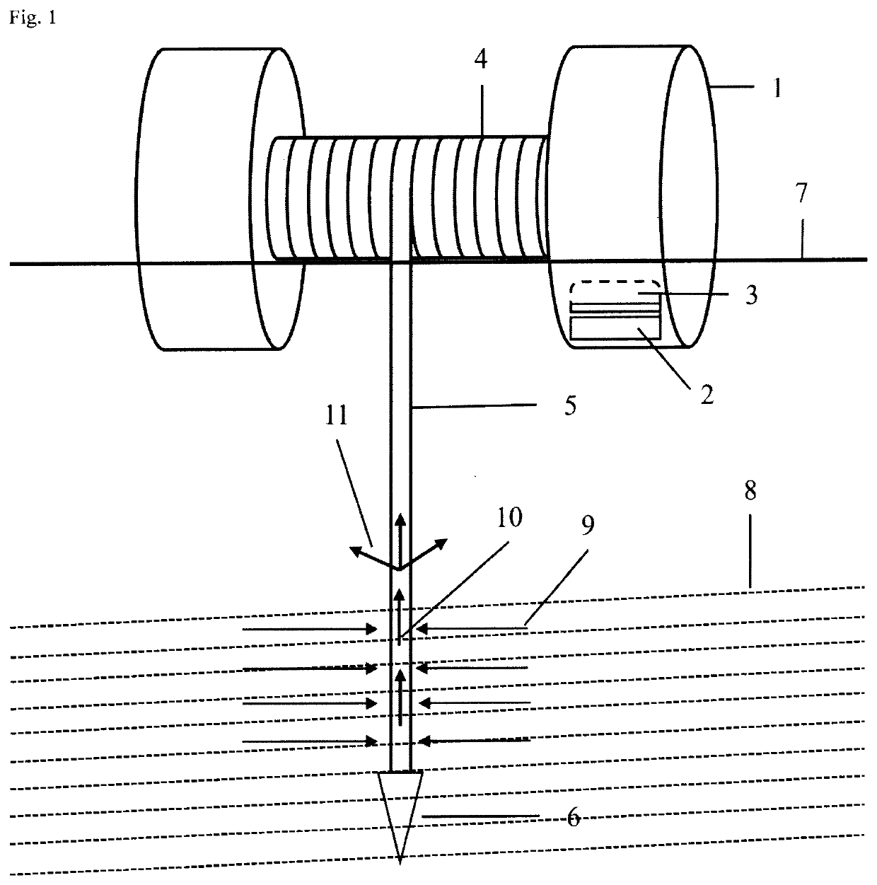
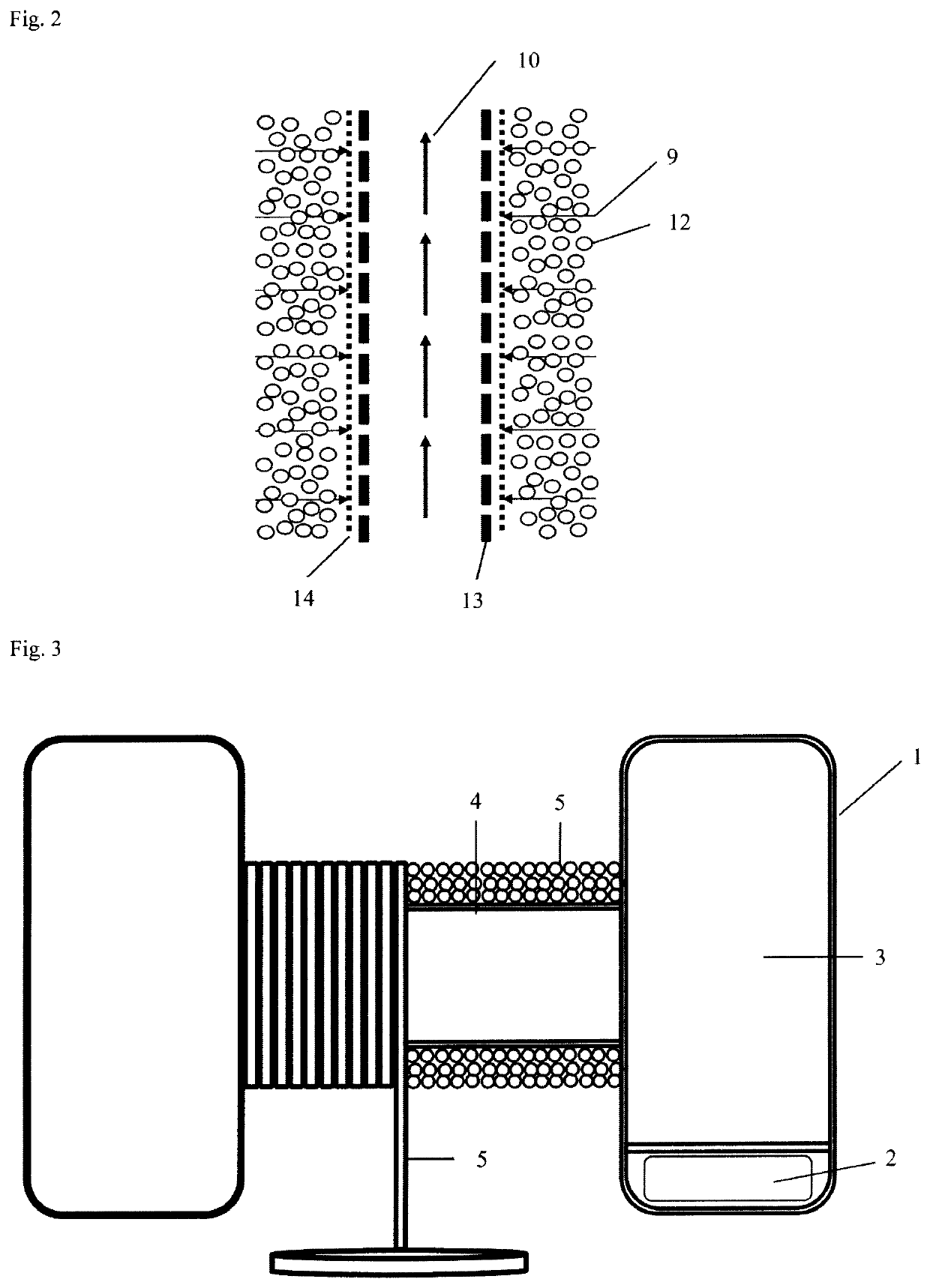
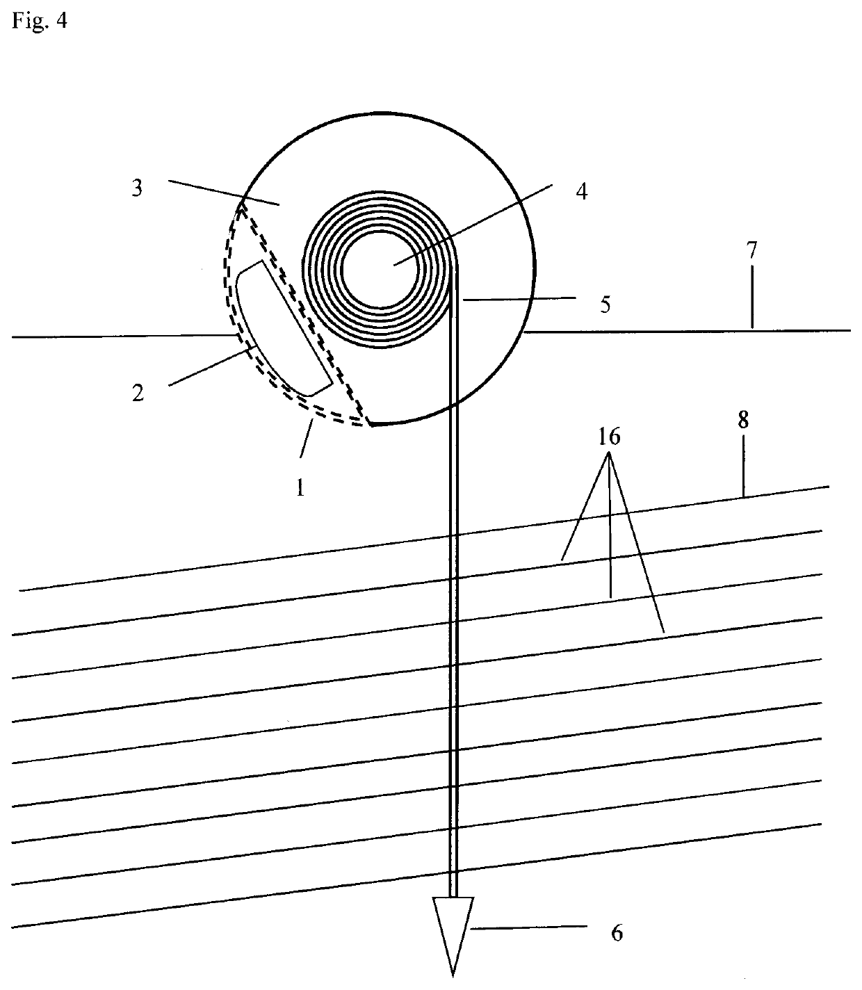
[0019]A system of components which facilitates the continuous release of trapped interstitial water from fine-grained sediments being actively deposited 16 in a containment facility (tailings storage facility) by creating a network of vertical drainage pathways in the sediment materials which are continuously extended upwards in tandem with pond or sediment elevation increases, connecting the surface or supernatant pond to all sediment horizons via a drainage pathway of relatively high hydraulic conductivity. The invention allows for the benefits of sediment consolidation and dewatering to be realized during the continued operation of a facility, and not only after the facility has completed operations and is preparing for remediation. The system is comprised of three primary components: a flotation device, an anchor mass, and a drainage conduit connecting the previous two components. The system extends upwards passively as the depth of sediment and or water increases. A description...


PUM

PropertyMeasurementUnit
specific gravityaaaaaaaaaa
lengthaaaaaaaaaa
buoyancyaaaaaaaaaa

Abstract

The Passive Tailings Compactor is a system of components for facilitating the continuous passive drainage and consolidation of fine-grained sediments in active and continuous deposition environments. The invention consists of a flotation device, an anchor mass, and a drainage conduit which acts as a tether between the flotation device and the anchor. The flotation device also serves to orient the drainage conduit horizontally. As water or sediment levels rise, the flotation device rotates, releasing drainage conduit wrapped around its axis. This allows the flotation device to move upwards, extending the drainage conduit passively. The flotation device uses asymmetrical fixed weights to resist lesser rotational forces. The drainage conduit serves to create a path of relatively high hydraulic conductivity, protected by a filter barrier, for the dissipation of pore pressures and consolidation of buried sediments. The anchor mass fixes the system in place.

Description

TECHNICAL FIELD[0001]Mineral processing (mining) and other industries often generate waste products in the form of continuously-produced fine-grained mineral sediments with high moisture contents. These sediments (tailings) create large volumes of materials which often have low hydraulic conductivities due to their fine particle size and high water contents as a result of their deposition via hydraulic transport. These materials are typically stored in large basins, behind earthen dams or dykes, which are constructed at significant cost. When these materials are deposited with increasing vertical depth, the result is often a mass of material containing excess interstitial water (water between solid particles of mineral) with a limited ability to drain itself. This trapped interstitial water results in inefficiencies due to the additional waste storage volume it occupies and the inability to reuse any of this trapped process water. Geotechnical stability risks related to storage basi...

Claims


Application Information

Patent Timeline
Patent Type & Authority Applications(United States)
IPC IPC(8): E02D3/10
CPCE02D3/103E02D2600/30E02D2300/0085E02D2300/0051B09B1/00B09B5/00B01D21/2444
Inventor BROWN, DOUG ROY
Owner PATRICK BROWN TECH INC
Why Eureka
Try Eureka