Universal Planar Membrane Device for Mass Transfer

a planar membrane and mass transfer technology, applied in the direction of membranes, electrochemical generators, separation processes, etc., can solve the problems of limiting the interchangeability of such cells, system not allowing access to the membrane, and cost of having designated equipment, so as to simplify the manufacture and assembly. , the effect of increasing the processing capacity of the device and achieving the same mass transfer or separation characteristics

Active Publication Date: 2021-03-11
MOLECULE WORKS INC
View PDF0 Cites 2 Cited by
  • Summary
  • Abstract
  • Description
  • Claims
  • Application Information

AI Technical Summary

Benefits of technology

[0010]One aspect of the design feature is usage of gasket sealing with bolts that simplifies the manufacture and assembly of the membrane module. In such a device, the thin membrane sheet may be fixed on a built-in supporting structure and separates two flow streams that may be termed the feed and sweep side. There may be straight channels for both the feed and sweep fluids to flow throughout the membrane surface from one end of the membrane to the opposite end of the membrane sheet at small pressure drops. The feed and sweep fluids can be configured as crossflow or countercurrent flow.
[0011]In an embodiment, the device may include one or multiple membrane sheets in parallel. Regardless of the number of the membrane sheets in the device, the device includes one inlet and one outlet port for the feed fluid, and one inlet and one outlet port for the sweep fluid. The membrane supporting structure, the feed flow channel structures, and sweep flow channel structures may be the same for one or multiple membrane sheets. Thus, the processing capacity of device can be increased by numbering up the membrane sheets while maintaining the same mass transfer or separation characteristics.
[0012]The device can be made of transparent polymer for clear visualization of the membrane channel and surface. The device can be made of metallic materials for operation at higher temperatures and / or higher pressures. Alternatively, the device may be made of ceramic materials.

Problems solved by technology

However, in single function for laboratory or small-scale applications it is costly to have designated equipment.
This type of system does not allow access to the membrane when maintenance is required.
With that type of membrane cells, customized membrane materials and configuration limit the ability to use such cells interchangeably.
However, making a new configuration for each different type of membrane materials is not cost-effective or may not even be viable.
The design of the device is more limited to relatively lower liquid flow rates.

Method used


Image

  • Universal Planar Membrane Device for Mass Transfer
  • Universal Planar Membrane Device for Mass Transfer
  • Universal Planar Membrane Device for Mass Transfer

Examples


example i

n for Online Removal of Fine Particulates from Process Stream

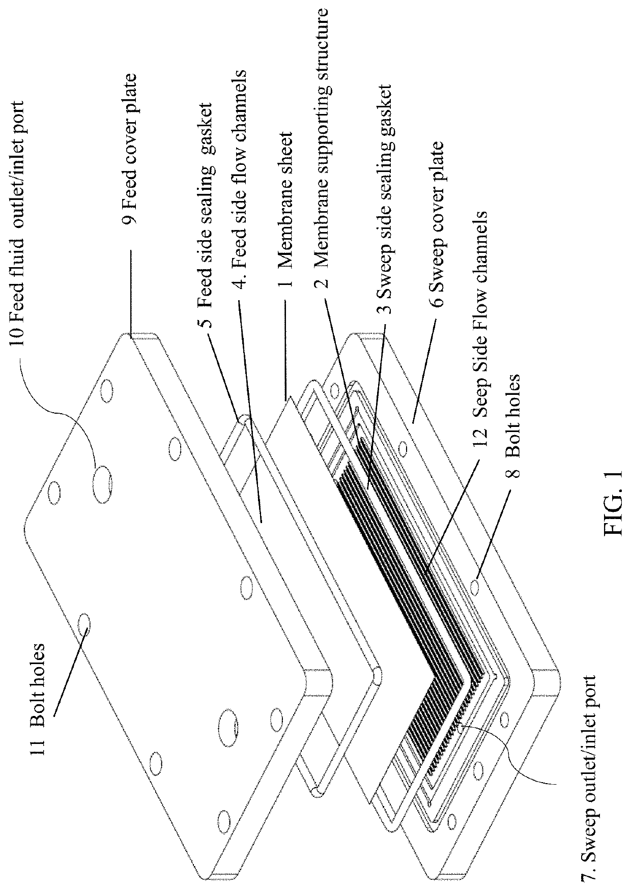
[0061]A device loaded with one membrane sheet 1 (FIG. 9), which is assembled as illustrated in FIG. 1, can be utilized for online filtration of fine particulates from different fluid streams—liquid (water, solvent, or oil, mixtures thereof) and from gases. Typically, any thin flat membrane 1 of 0.05-0.7 mm may be placed within the seating cavity on the sweep cover plate 6 and used depending on the application. In most of the tests shown here, a microporous nickel membrane ˜50 micron thick was used along with a polycarbonate cell 40. In applications involving prolonged exposure to temperatures above 60° C. or depending on chemical compatibility, a completely stainless-steel cell 40 was used. For particulates below 100 nm, YSZ ceramic coated microporous sheet membranes 1 were used. In these cases, the ceramic side is always placed facing the feed side of the cell 40. When used at higher temperatures, the inner silicone feed ...

example ii

xchange

[0068]For humidity and thermal exchange, the polycarbonate version of the device can be used (FIG. 11). It may be placed in any orientation. Ideally, the device should be placed in such a way that any condensation occurring due to high humidity can flow out of the cell 40 easily. The cell 40 may be assembled with a thin NaA zeolite membrane coated microporous nickel sheet. The cell 40 should be assembled such that the zeolite coating is facing the feed side of the cell 40. Humidified process air at different temperatures may be provided from using another cell 40 configured as a humidifier. That application is discussed in detail in Example 3. The humid process air may be flowed through the feed side of the device configured as a humidity and enthalpy exchanger. Humid house air at RH ˜40-50% may be swept through the sweep side at a range of flow rate from 0.5-7.5 NL / min to study the humidity and thermal exchange of the cell 40. Relative humidity (RH) and temperature of the ga...

example iii

midifier

[0069]FIG. 12 shows humidification of process gas using static water. In this example, static water on the feed side is used as the water source. A thin NaA zeolite coated microporous nickel membrane 1 may be used for this application, with the zeolite side always facing the feed. This membrane 1 selectively allows only water vapor permeation. The water for humidification may be fed to the cell 40 using gravity. The feed source may be kept elevated above the lower port of the cell 40. The cell 40 is kept vertically oriented and water enters the cell 40 at the bottom port 10. The water is fed either on the feed side or the sweep side, so it contacts either the zeolite or nickel side. Slight variation in performance is seen depending on the side the liquid water contacts. Care is taken to visually ensure there is no trapped gas on the water side. Gas to be humidified is flowed through the side that does not contain water. The test cell 40 was placed within an oven to maintain ...


PUM

PropertyMeasurementUnit
hydraulic diameteraaaaaaaaaa
thickaaaaaaaaaa
thicknessaaaaaaaaaa

Abstract

A membrane device is presented that can used for a wide range of applications from once-through filtration, crossflow filtration, molecular separation, gas/liquid absorption or reaction, gas dispersion into liquid, and degassing of liquid. The device comprises a thin flat sheet membrane that allows certain fluid or molecules go through while blocking others. The membrane sheet is fixed on a supporting structure with mini channel on two sides of the membrane for respective feed and sweep flows. The membrane sheet is sealed with gaskets with two cover plates that the membrane sheet can be replaced or cleaned. The cover plate provides connection ports to connect the feed fluid to the feed channels on one membrane surface and to connect the sweep fluid to the sweep channels on the other surface of the membrane.

Description

RELATED APPLICATIONS[0001]This application claims priority to U.S. Provisional Application No. 62 / 896,322 entitled “Universal Planar Membrane Device for Mass Transfer”, filed Sep. 5, 2019, the entire contents of which are hereby incorporated by reference for all purposes.FIELD OF THE INVENTION[0002]This invention relates to a device for selective mass exchange or transfer between two sides of a membrane.BACKGROUND[0003]Mass transfer management may be performed by filtration, molecular separation, dehumidification, humidification, gas / liquid contacting, and liquid / liquid contacting. Mass transfer management control may be provided by use of a membrane or media that allows only certain species or fluids to go through while blocking the others. In large-scale applications, a designated unit may be built to meet a specific application's needs. However, in single function for laboratory or small-scale applications it is costly to have designated equipment. A versatile and compact device ...

Claims


Application Information

Patent Timeline
Patent Type & Authority Applications(United States)
IPC IPC(8): B01D63/08B01D61/18
CPCB01D63/082B01D65/08B01D61/18B01D69/10B01D69/02B01D2325/24B01D71/022B01D71/028B01D69/12B01D71/36B01D65/02B01D2311/13B01D63/085B01D53/268B01D53/229B01D53/1475B01D53/263B01D53/18B01D2252/204B01D2252/2023B01D19/0031B01D17/085Y02E60/50Y02C20/40H01M8/04149B01D2315/22B01D2315/10B01D2313/143
Inventor LIU, WEIBALRAM, ANIRUDH
Owner MOLECULE WORKS INC
Why Eureka
Try Eureka