Check patentability & draft patents in minutes with Patsnap Eureka AI!

MEMS acoustic sensor

Active Publication Date: 2021-03-11
SHINSUNG SOUNDMOTION
View PDF0 Cites 1 Cited by
  • Summary
  • Abstract
  • Description
  • Claims
  • Application Information

AI Technical Summary

Benefits of technology

The present invention improves the structure of a MEMS acoustic sensor by optimizing anchor positions and increasing the coupling capacitance between the diaphragm and back plate, which increases the mechanical stability of the diaphragm against residual stress and over temperature change. The invention also provides a high sensitivity and stable sensing by eliminating the thermal stress or heat distortion effect generated in the diaphragm. The diaphragm has sufficient effective movable area larger than the cavity formed in the substrate, and support structures for supporting the diaphragm may be formed at the desired positions regardless of the size or position of the cavity. The invention minimizes the sensing error of the MEMS acoustic sensor by eliminating the thermal stress or heat distortion generated in the diaphragm before and after MEMS processes.

Problems solved by technology

Further, there is a limit in that the MEMS acoustic sensor provides high SNR and high sensitivity at the same time.
Therefore, a movable area of the diaphragm is also limited depending on the size of the cavity, and the support structure such as the anchor must be located in an area other than the cavity.
Such a structure not only restricts the degree of freedom in design but also has a limited sensor size or a limited cavity size.

Method used


Image

  • MEMS acoustic sensor
  • MEMS acoustic sensor
  • MEMS acoustic sensor

Examples


first embodiment

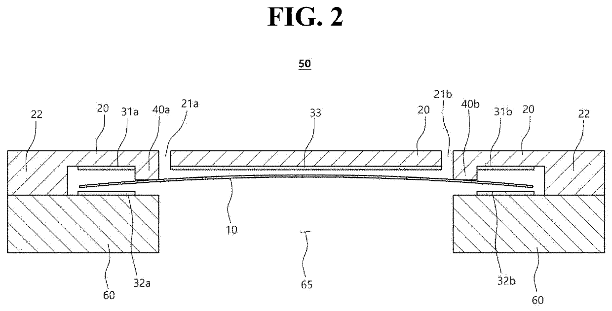
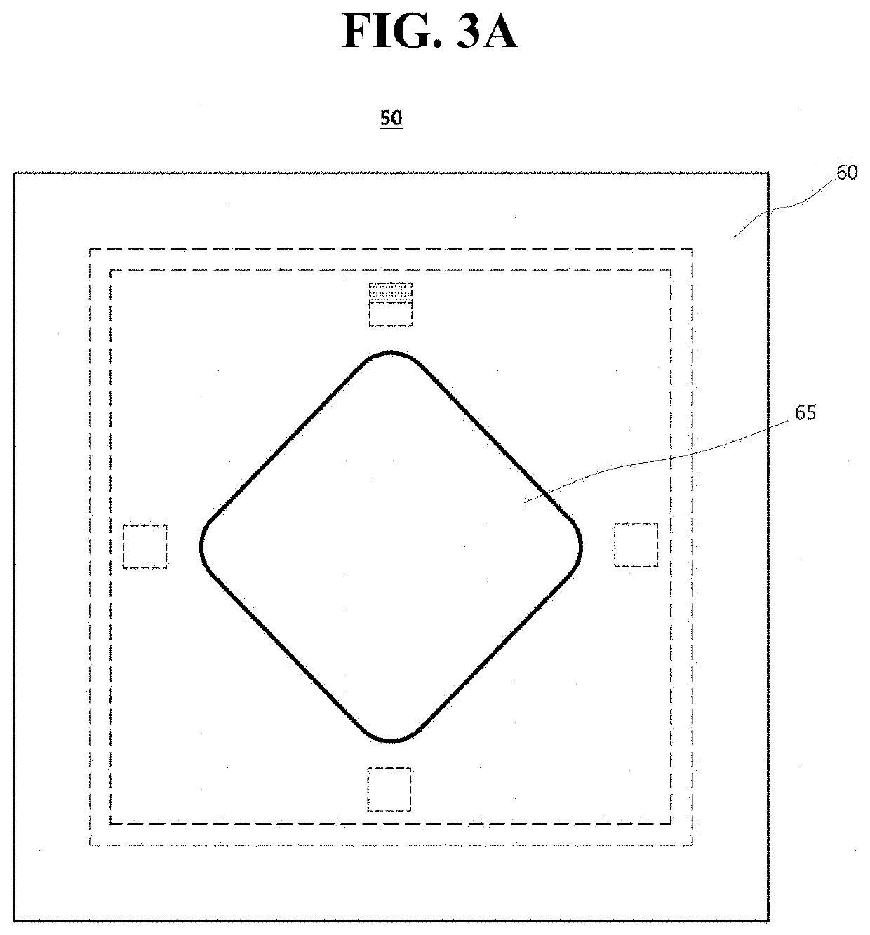
[0038]FIG. 2 is a plan view showing a MEMS acoustic sensor 50 according to the present invention. The MEMS acoustic sensor 50 may include a substrate 60 on which a cavity 65 is formed, a back plate 20 arranged on the substrate 60 and having a plurality of through-holes 21a and 21b, anchors 40a and 40b as support structures formed on the back plate 20 and protruding toward the substrate, and a diaphragm 10 supported on the anchors 40a and 40b and deformed by sound waves introduced through the cavity. Here, no part of the deformed diaphragm 10 comes into a direct contact with the substrate 60.

[0039]The diaphragm 10 may be made of, for example, a circular or rectangular polysilicon material, and may preferably have a square shape. However, it is not limited thereto, and naturally, the diaphragm 10 may be made of another material having flexibility, or may be formed of a polygon other than a circle or a square. Further, the coupling between the diaphragm 10 and the anchors 40a and 40b a...

second embodiment

[0050]FIG. 5A is a plan view showing a MEMS acoustic sensor 150 according to the present invention. The MEMS acoustic sensor 150 includes four anchors 140a, 140b, 140c, and 140d protruding from the back plate (not shown) in a direction to the substrate (not shown). Here, the cavity 65 formed in the substrate may have various shapes and sizes. However, considering the vibration mode of the rectangular diaphragm 110, it is preferable that it has a rhombic shape staggered with the rectangular diaphragm 110.

[0051]A cross-shaped incision line 115 is formed at the center of the diaphragm 110. The diaphragm 110 is supported by four anchors 140a, 140b, 140c, and 140d in an area between an end of the cross-shaped incision line 115 and an edge of the diaphragm 110 orthogonal thereto.

[0052]Also, the diaphragm 110 may be divided into four sub-areas 110a, 110b, 110c, and 110d based on the incision line 115. Specifically, the incision line 115 includes linear incision lines 115a, 115b, 115c, and ...

third embodiment

[0056]FIG. 6A is a plan view showing a MEMS acoustic sensor 250 according to the present invention.

[0057]The MEMS acoustic sensor 250 includes eight anchors 241a to 241d and 242a to 242d protruding from a rectangular diaphragm 210 and the back plate (not shown) in a direction of the substrate (not shown). Here, the cavity 65 formed in the substrate may have a rhombic shape staggered with the rectangular diaphragm 210 considering the vibration mode of the rectangular diaphragm 210.

[0058]Unlike the diaphragm 110 according to the second embodiment, the diaphragm 210 is completely separated into four sub-areas 210a, 210b, 210c, and 210d. Thus, the incision line 215 includes linear incision lines 215a, 215b, 215c, and 215d, each of which delimits two adjacent sub-areas. The diaphragm 210 is completely separated into four sub-areas 210a, 210b, 210c, and 210d by the four linear incision lines 215a, 215b, 215c, and 215d that meet at a center 215e.

[0059]Each sub-area 210a, 210b, 210c, and 2...


PUM


Abstract

Provided is a MEMS acoustic sensor including a substrate and a cavity, a back plate supported on the substrate and including a plurality of through-holes, at least one anchor projecting from the back plate toward the substrate, and a diaphragm supported by the at least one anchor and deformed by a sound wave introducing from the outside through the cavity, wherein no part of the deformed diaphragm comes into contact with the substrate.

Description

BACKGROUND1. Technical Field[0001]The present invention relates to an acoustic sensor implemented in a microelectromechanical system (MEMS), and more particularly, to a MEMS acoustic sensor for sensing a variable capacitance between a flexible diaphragm and a back plate.2. Description of the Related Art[0002]Generally, an acoustic sensor such as a condenser microphone converts a capacitance change, which is caused by a deformation of a diaphragm due to external sound pressure, to an electrical signal. It is attached to a microphone, a telephone, a mobile phone, a video tape recorder, and the like. Particularly, in recent years, such an acoustic sensor may be realized by micro-electromechanical system (MEMS) technology, thereby providing mass production and miniaturization.[0003]The MEMS acoustic sensor has a diaphragm that moves in response to sound pressure and a fixed opposing element that is acoustically transparent. The diaphragm functions as a moving electrode of a condenser mi...

Claims


Application Information

Patent Timeline
IPC IPC(8): H04R19/04H04R19/00H04R1/04H04R7/16B81B3/00
CPCH04R19/04H04R19/005H04R1/04H04R7/16B81B2203/04H04R2201/003B81B2201/0257B81B2203/0127B81B2203/0307B81B3/0037
Inventor LEE, SANG WOOSONG, CI MOOYOUN, KEUN JUNGKIM, YONG KOOKJUNG, KYU DONGSHAH, MUHAMMAD ALI
Owner SHINSUNG SOUNDMOTION
Features
  • R&D
  • Intellectual Property
  • Life Sciences
  • Materials
  • Tech Scout
  • Unparalleled Data Quality
  • Higher Quality Content
  • 60% Fewer Hallucinations
Learn More