Nonaqueous electrolyte energy storage device and method for manufacturing nonaqueous electrolyte energy storage device

a technology of nonaqueous electrolyte and energy storage device, which is applied in the direction of cell components, final product manufacturing, sustainable manufacturing/processing, etc., can solve the problems of deterioration of charge-discharge performance, and achieve the effect of greatly increasing the internal resistance after a charge-discharge cycl

Inactive Publication Date: 2021-04-01
GS YUASA INT LTD
View PDF0 Cites 0 Cited by
  • Summary
  • Abstract
  • Description
  • Claims
  • Application Information

AI Technical Summary

Benefits of technology

[0020]According to the nonaqueous electrolyte energy storage device, it becomes possible to prevent the oxidation / corrosion of aluminum and to prevent the increase in the internal resistance after a charge-discharge cycle even when the concentration of an imide salt in a nonaqueous electrolyte is not increased. In the nonaqueous electrolyte energy storage device, the reason why the above-mentioned advantageous effects can produced is unclear, but the following reasons are assumed. When a positive electrode mix is formed using a positive electrode mix paste containing an oxoacid of phosphorus, a coating film is formed which contains a component having such a property that a peak attributed to P2p appears at a position corresponding to 135 eV or less in an X-ray photoelectron spectroscopic spectrum coming from the oxoacid of phosphorus. It is assumed that the coating film can prevent the oxidation / corrosion of aluminum that serves as a positive electrode base material or the like and consequently the internal resistance cannot be increased and the increase in the internal resistance after a charge-discharge cycle can be prevented. The reason for these phenomena is unclear. However, the effect that the increase in the internal resistance after a charge-discharge cycle can be prevented is a special effect that can be achieved only when an imide salt is used as an electrolyte salt and a positive electrode mix having such a property that a peak attributed to P2p appears at a position corresponding to 135 eV or less in the X-ray photoelectron spectroscopic spectrum is used. According to the nonaqueous electrolyte energy storage device, the capacity retention rate after a charge-discharge cycle can also be increased. The reason when the capacity retention rate is increased is also unclear. However, it is assumed to be because a coating film containing a component having such a property that a peak attributed to P2p appears at a position corresponding to 135 eV or less in the X-ray photoelectron spectroscopic spectrum can also prevent the oxidation / corrosion of aluminum. According to the nonaqueous electrolyte energy storage device, it becomes possible, for example, to prevent the increase in the internal resistance after a charge-discharge cycle even when the concentration of the imide salt is not increased as mentioned above. Therefore, the nonaqueous electrolyte energy storage device can improve the disadvantages, e.g., high viscosity and high internal resistance, of a conventional nonaqueous electrolyte energy storage device including an imide salt at a high concentration, and can be used suitably even when the nonaqueous electrolyte energy storage device is so designed as to contain the imide salt at a concentration falling within a range that does not deemed as a high concentration range.
[0021]A sample (a positive electrode mix) to be used in the measurement of an X-ray photoelectron spectroscopic spectrum can be prepared in the following manner. A nonaqueous electrolyte energy storage device is discharged at a current of 0.1 C to an end-of-discharge voltage employed in the conventional use to make the nonaqueous electrolyte energy storage device in a completely discharged state. The energy storage device in the completely discharged state is broken down to remove a positive electrode, and the positive electrode is fully washed with dimethyl carbonate and is then dried under reduced pressure at room temperature. The dried positive electrode is cut into a predetermined size (e.g., 2×2 cm), and is used as a sample for the measurement of an X-ray photoelectron spectroscopic spectrum. The operations from the breaking down of the nonaqueous electrolyte energy storage device to the preparation of the sample to be used in the measurement of an X-ray photoelectron spectroscopic spectrum are carried out in an argon atmosphere at a dew point of −60° C. or lower, and the produced sample was enclosed in a transfer vessel, is then held in an argon atmosphere at a dew point of −60° C. or lower and is then introduced into a sample chamber in an X-ray photoelectron spectroscopic spectrum measurement device. The device and the measurement conditions to be employed in the measurement of an X-ray photoelectron spectroscopic spectrum are as follows.
[0026]Measurement range: P2p=145 to 128 eV, C1s=300 to 272 eV
[0030]The position of a peak in the spectrum is a value determined in the following manner. Firstly, the position of a peak of C1s which is attributed to sp2 carbon is defined as 284.8 eV, and the binding energies of all of the obtained spectra are corrected on the basis of this definition. Next, a background is removed from each of the corrected spectra by a straight line method. In this manner, a leveling processing of the spectra is carried out. A binding energy at which the intensity of a peak attributed to P2p becomes highest in the spectra obtained after the leveling processing is defined as the position of a peak attributed to P2p.
[0031]In the nonaqueous electrolyte energy storage device, it is preferred that the content of the imide salt in the nonaqueous electrolyte is 0.5 mol / kg or more and 2 mol / kg or less. According to the nonaqueous electrolyte energy storage device, the oxidation / corrosion of aluminum can be prevented even when the imide salt is used at a concentration falling within the above-mentioned range that is not deemed as a high concentration range. Therefore, in the nonaqueous electrolyte energy storage device, it is not needed to use the imide salt at a high concentration. In general, when an imide salt is used at a high concentration, the viscosity is increased and the internal resistance is also increased. In contrast, in the nonaqueous electrolyte energy storage device, when the concentration of the imide salt in the nonaqueous electrolyte falls within a range that is not deemed as a high concentration range like the above-mentioned range, the internal resistance is not increased and the increase in the internal resistance after a charge-discharge cycle can be prevented. Furthermore, the viscosity of a nonaqueous electrolyte containing the imide salt at a concentration falling within the above-mentioned range that does not deemed as a high concentration range is small. Therefore, it is expected that the high-rate-discharge performance at a lower temperature and the like can be improved.
[0032]In the nonaqueous electrolyte energy storage device, the maximum reached potential of the positive electrode is preferably 4.4 V (vs. Li / Li+) or more, more preferably 4.5 V (vs. Li / Li+) or more, still more preferably 4.6 V (vs. Li / Li+) or more. According to the nonaqueous electrolyte energy storage device, even in such charge-discharge that the maximum reached potential of the positive electrode at which the oxidation / corrosion of aluminum is likely to be caused remarkably when the imide salt is used becomes 4.4 V (vs. Li / Li+) or more, it becomes generally possible to decrease the internal resistance after a charge-discharge cycle. Therefore, when the maximum reached potential of the positive electrode is adjusted to 4.4 V (vs. Li / Li+) or more, the capacity can be increased by the charge / discharge of the positive electrode at an operation potential of 4.4 V (vs. Li / Li+) or more while preventing the increase in the internal resistance after a charge-discharge cycle.

Problems solved by technology

Li / Li+) or more and consequently the charge-discharge performance may be deteriorated.

Method used


Image

  • Nonaqueous electrolyte energy storage device and method for manufacturing nonaqueous electrolyte energy storage device

Examples


example 1

(Preparation of Nonaqueous Electrolyte)

[0099]Lithium bis(fluorosulfonyl)imide (LiFSI) that served as an electrolyte salt was dissolved at a concentration of 1.0 mol / kg in a mixed solvent prepared by mixing fluoroethylene carbonate (FEC) with methyl trifluoroethyl carbonate (MFEC) at a volume ratio of 3:7 to prepare a nonaqueous electrolyte.

(Manufacture of Nonaqueous Electrolyte Energy Storage Device)

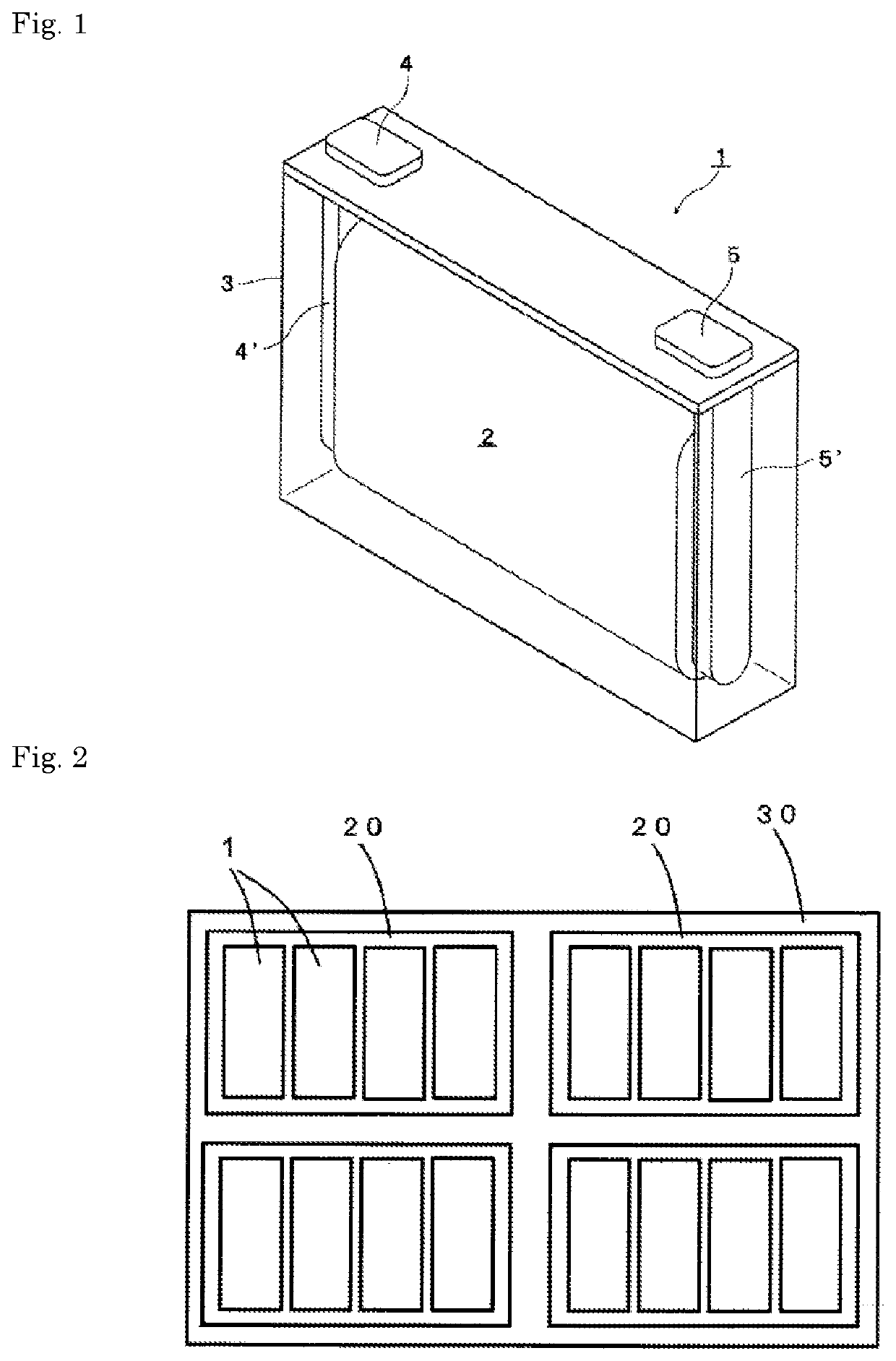
[0100]The positive electrode P1 and the negative electrode were laminated on each other with a separator that was a polyolefin-made microporous film interposed therebetween to manufacture an electrode assembly. The electrode assembly was enclosed in a container made from a metal-resin composite film, then the nonaqueous electrolyte was injected into the inside of the container, and then an opening of the container was sealed by heat sealing to manufacture a nonaqueous electrolyte energy storage device (a laminated nonaqueous electrolyte secondary battery) of Example 1.

examples 2 to 6

, Comparative Examples 1 to 6, Reference Examples 1 to 2

[0101]Nonaqueous electrolyte energy storage devices of Examples 2 to 6, Comparative Examples 1 to 6 and Reference Examples 1 to 2 were manufactured in the same manner as in Example 1, except that the types of the positive electrodes and the electrolyte salts, the types of the solvents and the volume-based mixing ratios shown in Tables 1 to 3 were employed.

[0102]The solvents shown in the tables are the following compounds.

[0103]FEC: fluoroethylene carbonate

[0104]MFEC: methyl trifluoroethyl carbonate

[0105]TFEE: 1,1,2,2-tetrafluoroethyl-2,2,2-trifluoroethyl ether

[0106]EMC: ethyl methyl carbonate

[0107]EC: ethylene carbonate

[Evaluation 1] Range of Charge-Discharge Voltage: 4.6 to 2.0 V

(Initial Charge-Discharge)

[0108]Each of the nonaqueous electrolyte energy storage devices of Examples 1 to 4, Comparative Examples 1 to 4 and Reference Examples 1 to 2 was subjected to initial charge-discharge under the following conditions. Each of th...


PUM

PropertyMeasurementUnit
positive electrode potentialaaaaaaaaaa
sizeaaaaaaaaaa
binding energiesaaaaaaaaaa

Abstract

One aspect of the present invention is a nonaqueous electrolyte energy storage device including: a positive electrode including a positive electrode mix containing a phosphorus atom; and a nonaqueous electrolyte containing an imide salt, wherein a peak attributed to P2p appears at a position corresponding to 135 eV or less in an X-ray photoelectron spectroscopic spectrum of the positive electrode mix. Another aspect of the present invention is a method for manufacturing a nonaqueous electrolyte energy storage device including: a positive electrode including a positive electrode mix produced using a positive electrode mix paste containing an oxoacid of phosphorus; and a nonaqueous electrolyte containing an imide salt.

Description

TECHNICAL FIELD[0001]The present invention relates to a nonaqueous electrolyte energy storage device and a method for manufacturing a nonaqueous electrolyte energy storage device.BACKGROUND ART[0002]A nonaqueous electrolyte secondary battery typified by a lithium ion secondary battery is often used in an electronic device such as a personal computer and a communication terminal, an automobile and others due to the high energy density thereof. In general, the nonaqueous electrolyte secondary battery is equipped with a pair of electrodes that are electrically separated from each other through a separator and a nonaqueous electrolyte arranged between the electrodes, and is configured so as to be charged and discharged through the acceptance and reception of ions between the electrodes. As a nonaqueous electrolyte energy storage device other than the nonaqueous electrolyte secondary battery, a capacitor such as a lithium ion capacitor and an electric double-layer capacitor has also been...

Claims


Application Information

Patent Timeline
Patent Type & Authority Applications(United States)
IPC IPC(8): H01M4/36H01M4/133H01M10/0525H01M10/058
CPCH01M4/364H01M4/133H01M2004/028H01M10/058H01M10/0525H01M4/62H01M10/0568Y02E60/10H01M4/1391H01M4/366H01M4/525H01M10/052H01M2300/0034H01M2300/0037H01M10/0569Y02P70/50H01M4/628H01M4/661H01M4/662H01M10/4235H01M4/505H01M4/5825H01M4/131H01M4/136H01M4/1315H01M4/66
Inventor TAKAHASHI, KATSUYUKIKIKUCHI, AKIFUMI
Owner GS YUASA INT LTD
Why Eureka
Try Eureka