

Gas sensor
a technology of gas sensor and sensor, which is applied in the field of gas sensor, can solve the problems of tens to hundreds of mega q, the resistance of the resulting nano-gold thin film being too high and difficult to control, and people facing enormous difficulties in designing back-end signal processing circuits
- Summary
- Abstract
- Description
- Claims
- Application Information
AI Technical Summary
Benefits of technology
Problems solved by technology
Method used
Image

Examples
example 1
[0036]Measurement of Baseline Resistances of Gas Sensors
[0037]Example 1 illustrates the influence of the metal layer doped with conjugated molecules in the gas sensor on the baseline resistance of the gas sensor. First, Sensor C, Sensor I, Sensor II, Sensor III, and Sensor IV were provided. In Example 1, the metal layers in the gas sensors described above were mainly formed of nano-gold particles with octyl groups attached to the surface. The metal layer of Sensor C was not doped with conjugated molecules. The metal layers of Sensors I to IV were doped with conjugated molecules
where R was —O—(CH2)3CH3. The doping concentration ratios were 1:20 (Sensor I), 1:100 (Sensor II), 1:2,000 (Sensor III), and 1:10,000 (Sensor IV). The baseline resistances of the gas sensors were measured, and the measurement results are shown in Table 1.
TABLE 1Gas SensorDoping Concentration RatioBaseline ResistanceSensor C0~500MΩSensor I1:20 11.3 ± 1.1MΩSensor II1:100 3.01 ± 0.14MΩSensor III1:2,000 0.72 ± ...
example 2
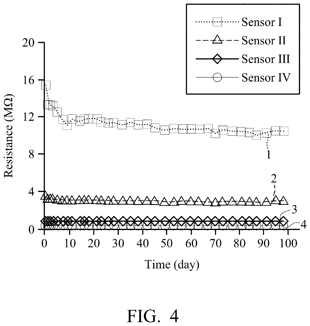
[0039]Measurement of Service Lives of Gas Sensors
[0040]Example 2 illustrates the influence of the metal layers doped with conjugated molecules in the gas sensors on the service lives of the gas sensors. First, Sensor I, Sensor II, Sensor III, and Sensor IV were provided. In Example 2, the metal layers in the gas sensors described above were mainly formed of nano-gold particles with octyl groups attached to the surface. The metal layers of Sensors I to IV were doped with conjugated molecules
where R was —O—(CH2)3CH3. The doping concentration ratios were 1:20 (Sensor I), 1:100 (Sensor II), 1:2,000 (Sensor III), and 1:10,000 (Sensor IV). The service lives of the gas sensors were measured, and the measurement results are shown in FIG. 4.
[0041]In FIG. 4, Curve 1 shows the change in the resistance of Sensor I over time. Curve 2 shows the change in the resistance of Sensor II over time. Curve 3 shows the change in the resistance of Sensor III over time. Curve 4 shows the change in the resis...
example 3
[0042]Measurement of Sensitivities of Gas Sensors
[0043]Example 3 illustrates the influence of the metal layers doped with conjugated molecules in the gas sensors on the sensitivities of the gas sensors. First, Sensor C and Sensor II were provided. In Example 3, the metal layers in the gas sensors described above were mainly formed of nano-gold particles with octyl groups attached to the surface. The metal layer of Sensor C was not doped with conjugated molecules. The metal layer of Sensor II was doped with conjugated molecules
where R was —O—(CH2)3CH3. The doping concentration ratio was 1:100. A target gas (e.g. toluene) with a concentration between 400 ppm and 1,000 ppm was then introduced into the gas sensors and the sensitivities of gas sensors were measured. 400, 500, 600, 800, and 1,000 ppm of toluene gases were introduced at 100, 300, 500, 700, and 900 seconds, respectively. The measurement results are shown in FIG. 5.
[0044]In FIG. 5, Curve 1 shows the change in the resistance ...
PUM
 Abstract
Description
Claims
Application Information