Co to co2 combustion promoter

a technology of co2 and promoter, which is applied in the direction of metal/metal-oxide/metal-hydroxide catalyst, physical/chemical process catalyst, separation process, etc., can solve the problem of high residual concentration of carbon monoxide in flue gases from regenerators, significant damage to plant equipment, and large amounts of noble metals, etc. problems, to achieve the effect of less nox formation, less diffusion limitation, and higher loading

Active Publication Date: 2021-06-03
COCHISE TECH LLC
View PDF0 Cites 0 Cited by
  • Summary
  • Abstract
  • Description
  • Claims
  • Application Information

AI Technical Summary

Benefits of technology

[0013]A further advantage with the eggshell of noble metal is that less NOx formation is achieved. This may be explained as follows. NOx forming reactions are slower and thus less diffusion limited than the CO to CO2 reactions. Thus, the prior art combustion promoters having a uniform distribution and higher loading of the noble metal will generate more NOx as this additional noble metal will catalyse NOx forming reactions.

Problems solved by technology

High residual concentration of carbon monoxide in flue gases from regenerators has been a problem.
Afterburning has caused significant damage to plant equipment.
A disadvantage of all noble metal based CO to CO2 combustion promoters is that relatively large amounts of noble metal are required to achieve the desired CO combustion in the FCC process.

Method used


Image

  • Co to co2 combustion promoter
  • Co to co2 combustion promoter
  • Co to co2 combustion promoter

Examples


example 1

[0061]A two-step impregnation was carried out using a high purity gamma alumina support as purchased from Sasol. In the first step, 10 g of alumina powder was impregnated with water to fill 90% of the pore volume. At a pore volume of 0.5 mL / g, 4.5 mL of water was required for 10 g of alumina powder. For the second step, the wet alumina particles from step 1 with 90% of the pore volume filled with water were impregnated with a solution of palladium nitrate and dried to achieve an eggshell of palladium on the particle surface. The second impregnation step was completed before the pre-filled alumina particles were dried. After completing both impregnation steps, the impregnated particles were calcined at 600° C. for 1 hour to form a particle with the composition in accordance with this invention.

example 2

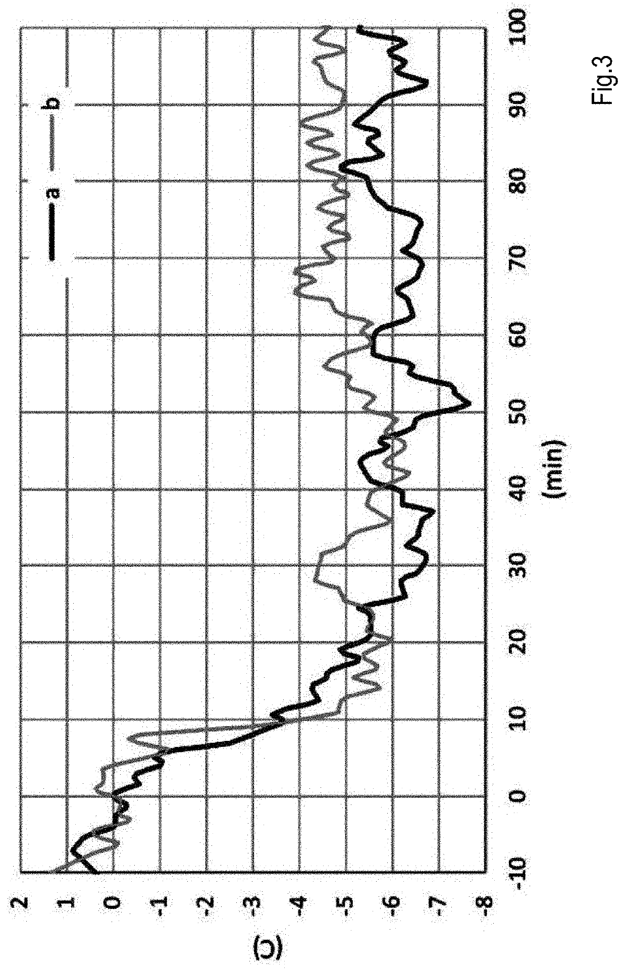
[0062]0.1 g of the composition of Example 1 was mixed with 10 g of a commercial FCC catalyst. The mixture was then used to measure the oxidation of CO in a fluid bed reactor fitted with a thermocouple. The catalyst bed was heated to 600° C. prior to the start of CO / O2 flow. Oxidation response was measured using a mixture of 1.8 v / v % CO and 0.9 v / v % 02, balanced with He, under a gas flow rate of 1000 cc / min. The oxidation response is a measure of the amount of CO which is combusted (oxidized) to CO2.

example 3

[0065]A two-step impregnation was carried out using a high purity gamma alumina support as purchased from Sasol. In the first step, 10 g of alumina powder was impregnated with water to fill 90% of the pore volume. At a pore volume of 0.5 mL / g, 4.5 mL of water was required for 10 g of alumina powder. For the second step, the wet alumina particles from step 1 with 90% of the pore volume filled with water were impregnated with a solution of platinum nitrate and dried to achieve an eggshell of platinum on the particle surface. The second impregnation step was completed before the pre-filled alumina particles were dried. After completing both impregnation steps, the impregnated particles were calcined at 600° C.


PUM

PropertyMeasurementUnit
sizeaaaaaaaaaa
sizeaaaaaaaaaa
particle sizeaaaaaaaaaa

Abstract

The invention is directed to a CO to CO2 combustion promoter comprising microsphere sized porous silica and / or alumina comprising particles further comprising on or more Group VIII noble metals wherein the noble metal is distributed in the particle as an eggshell such that a higher content of noble metal is present in the outer region of the particle as compared to the content of noble metal in the center of the particle.

Description

CROSS-REFERENCE TO RELATED APPLICATIONS[0001]This application is a continuation under 35 U.S.C. § 120 of co-pending U.S. application Ser. No. 17 / 043,031 filed Sep. 29, 2020, which is a 35 U.S.C. § 371 National Phase Entry Application of International Application No. PCT / US2019 / 024742 filed Mar. 29, 2019, which designates the U.S. and claims benefit under 35 U.S.C. § 119(a) of N.L. Provisional Application No. 2020819 filed Apr. 24, 2018 and under 35 U.S.C. § 119(e) of U.S. Provisional Application No. 62 / 651,295 filed Apr. 2, 2018, the contents of which are incorporated herein by reference in their entireties.FIELD OF THE INVENTION[0002]The invention is directed to a CO to CO2 combustion promoter comprising microsphere sized porous alumina particles comprising one or more Group VIII noble metals.BACKGROUND OF THE INVENTION[0003]Such CO to CO2 combustion promoters are well known and are used in a fluid catalytic cracking (FCC) unit. In such a FCC process fluidizable catalyst particles ...

Claims


Application Information

Patent Timeline
Patent Type & Authority Applications(United States)
IPC IPC(8): B01J23/89B01J35/08B01J23/42B01J23/63B01J35/10B01J35/00B01J21/04B01J23/44B01J37/02C10G11/04B01J21/12B01J8/26B01J21/08B01J8/18B01J37/08C01B32/50
CPCB01J23/8926B01J35/1038B01J23/42B01J23/63B01J35/1014B01J35/008B01J21/04B01J23/44B01J37/0236C10G11/04B01J21/12B01J8/26B01J21/08B01J8/1827B01J37/088C01B32/50B01J37/0221B01J35/1019B01J35/08B01J35/002B01J35/023B01J37/0045B01J37/0201B01J37/0205B01J23/894B01J35/0026B01J37/0207B01D53/864B01D2255/1021B01D2255/1023B01D2255/2092C10G11/18C10G11/02Y02P30/40
Inventor ARU, GUIDO WILLIAM
Owner COCHISE TECH LLC
Why Eureka
Try Eureka