Method and Apparatus for Removal of Per- and Polyfluoroalkyl Substances (PFAS) from Groundwater

a technology of polyfluoroalkyl substances and groundwater, applied in the field of groundwater remediation systems, can solve the problems of contaminated groundwater plumes, ineffective in-situ remediation techniques, and high cost of pfas source zones and plumes

Pending Publication Date: 2021-07-15
GSI ENVIRONMENTAL
View PDF5 Cites 1 Cited by
  • Summary
  • Abstract
  • Description
  • Claims
  • Application Information

AI Technical Summary

Benefits of technology

[0017]The primary advantage of the invention is to provide a system for concentration, displacement, sequestering, and / or removal of high PFAS concentration groundwater and buoyant material that has been concentrated by the sparging.
[0018]Another advantage of the invention is to provide a system to sequester PFAS without the necessity of extracting groundwater.
[0019]Yet another advantage of the invention is to provide a removal through a permeable trench or above ground trench of a high PFAS concentration groundwater layer that has been concentrated by the sparging and collection.
[0020]Yet another advantage of the invention is to provide a removal by phytoremediation of a high PFAS concentration groundwater layer that has been concentrated by the sparging and collection.
[0021]In accordance with a preferred embodiment of the invention, there is shown a method for the decontamination of a subsurface aquifer containing one or more PFAS contaminants, having the steps of injecting gas through a screened well or open tube and into the aquifer through a natural aquifer material so as to form a buoyant material in the aquifer, the one or more PFAS contaminants accumulating in the buoyant material, allowing the buoyant material to rise to the water table or the top of a confined aquifer where some of the PFAS will desorb from the buoyant material, concentrating the PFAS in the shallow groundwater, and extracting the groundwater near the water table or top of the confined aquifer that contains the concentrated PFAS.
[0022]In accordance with another preferred embodiment of the invention, there is shown a method for the decontamination of a subsurface aquifer containing one or more PFAS contaminants, having the steps of injecting gas into the aquifer through a natural aquifer material so as to form a buoyant material in the aquifer, the one or more PFAS contaminants accumulating on the buoyant material, allowing the buoyant material to rise to the water table or the top of a confined aquifer where some of the PFAS will desorb, concentrating the PFAS in the shallow groundwater, and extracting the groundwater near the water table or top of the confined aquifer that contains the concentrated PFAS.

Problems solved by technology

These factors have led some to speculate that sources of PFAS to groundwater may result in contaminated groundwater plumes that are similar or larger than plumes generated by releases of other well-known groundwater contaminants such as gasoline constituents and chlorinated solvents.
Three factors make complete in-situ remediation of PFAS source zones and plumes exceptionally costly and potentially impracticable at many sites.
First, the chemical properties that make PFAS mobile and persistent in groundwater make many commonly used in-situ remediation technologies ineffective, such as bioremediation, many forms of chemical oxidation, chemical reduction, and thermal treatment.
Current groundwater remediation technologies that destroy contaminants in-situ are not effective for PFAS source zones or plumes.
For example, bioremediation cannot be employed because, while some PFAS can partially biodegrade, they do not completely biodegrade.
Thermal treatment is ineffective because these compounds are much less volatile than conventional groundwater contaminants and cannot be destroyed at the range of temperatures induced by in-situ thermal treatment.
Groundwater circulation well (GCW) technology was tested extensively in the 1990s and was generally found to be unsuccessful as a groundwater remediation method.
Few sites have been clear successes and just as many seem to have been clear failures, the preponderance, however, are blurred into the middle, attaining some contaminant reduction but lacking the data to allow for validation of the technology's efficacy.
The wide-scale use of GCW seems limited by a general uncertainty and skepticism about the technology's true performance.
In the absence of well documented examples of successful demonstrations, the use of GCW technology will likely continue to be limited, at least on federal sites.”
Because of these limitations, cleanup processes that rely on subsurface groundwater recirculation will likely have limited usefulness for widespread PFAS groundwater cleanup problems.
Ross et al., (2018) noted that sparging outside the well annulus has not been successfully accomplished: “Thus far, this technology has not given consideration to achieving an ROI outside of the well annulus for either injecting air or collecting the foam concentrate.” (ROI: Radius of Influence).
The lack of effective in-situ remediation technologies means that most PFAS plumes that require remediation are managed using inefficient groundwater pump-and-treat systems (FIG. 1), where large volumes of low concentration groundwater are extracted over decades to remove contaminant mass and prevent further plume migration.
One in-situ stabilization technology, the injection of colloidal granular activated carbon (GAC), has shown some ability to reduce the mass flux of PFAS plumes, but may not be a permanent solution if the GAC becomes saturated with PFAS or non-PFAS constituents moving through groundwater.
In summary, there are currently no cost-effective in-situ treatment technologies for PFAS, making PFAS cleanup sites more difficult and expensive to manage than many other groundwater contamination sites.

Method used


Image

  • Method and Apparatus for Removal of Per- and Polyfluoroalkyl Substances (PFAS) from Groundwater
  • Method and Apparatus for Removal of Per- and Polyfluoroalkyl Substances (PFAS) from Groundwater
  • Method and Apparatus for Removal of Per- and Polyfluoroalkyl Substances (PFAS) from Groundwater

Examples


Embodiment Construction

:

[0039]Detailed descriptions of the preferred embodiment are provided herein. It is to be understood, however, that the present invention may be embodied in various forms. Therefore, specific details disclosed herein are not to be interpreted as limiting, but rather as a basis for later filed claims and as a representative basis for teaching one skilled in the art to employ the present invention in virtually any appropriately detailed system, structure, method or manner.

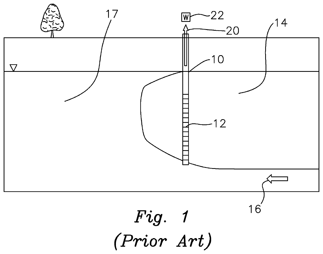
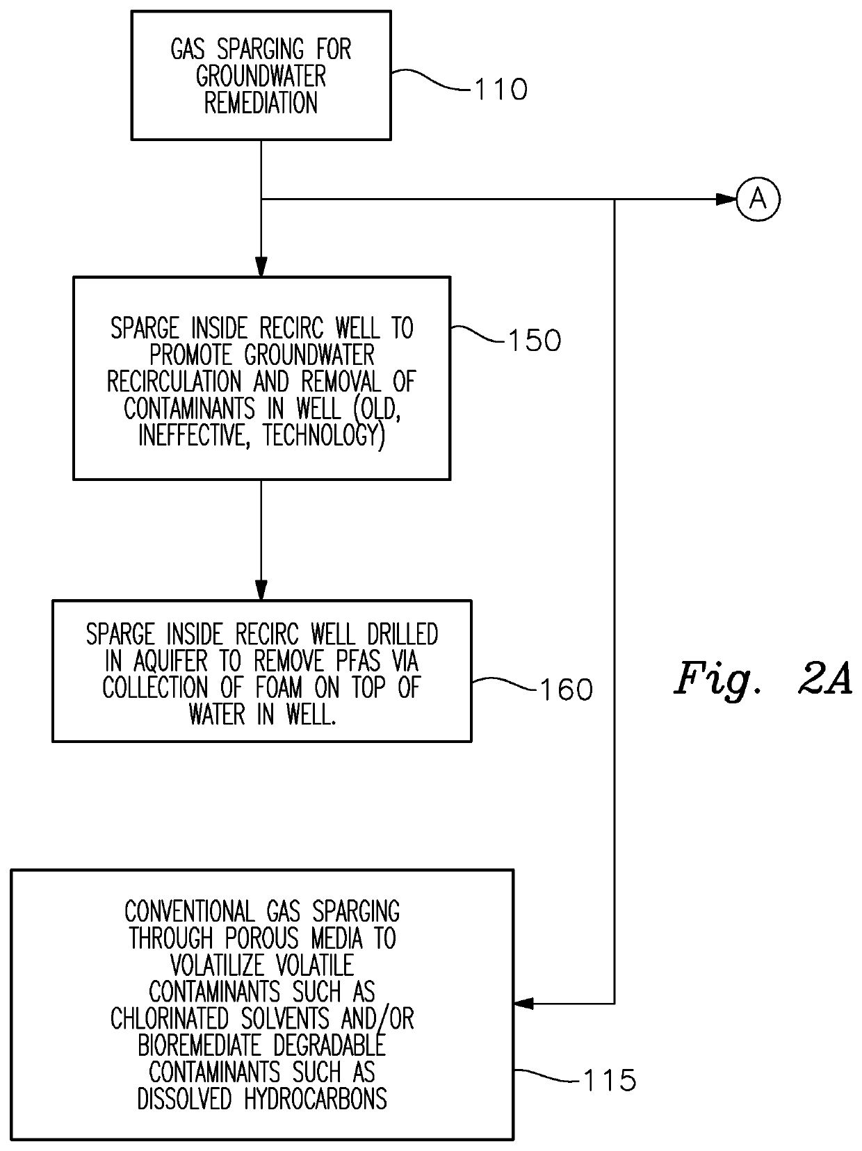
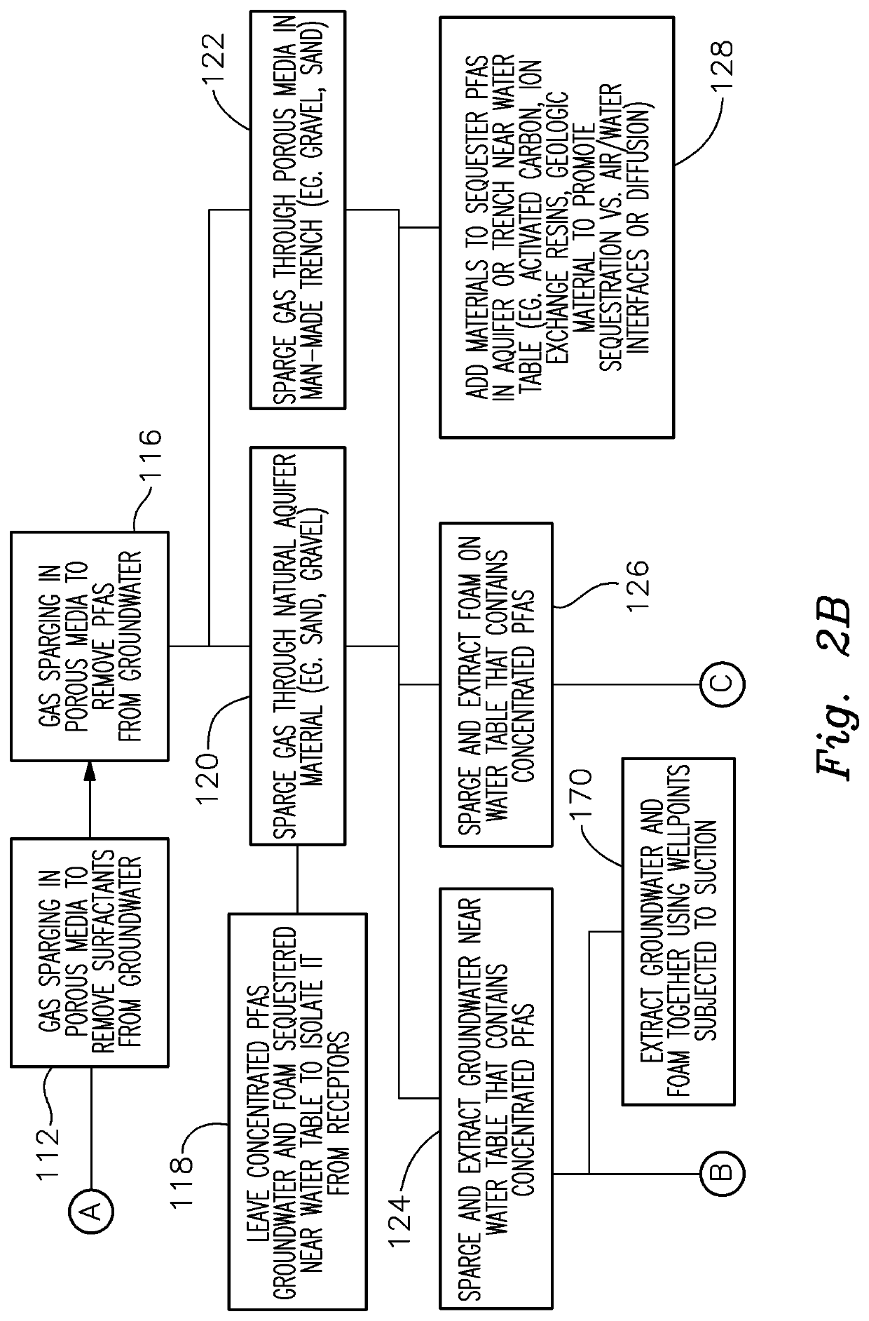
[0040]A process of a preferred embodiment is disclosed for the in-situ concentration of PFAS in groundwater to: 1) reduce the volume of contaminated plume; and / or 2) reduce the amount of contaminated groundwater that needs to be treated; 3) sequester PFAS in the subsurface for long periods to preclude their migration to receptors; and / or 4) to facilitate the removal of PFAS from the subsurface. The process relies on the in-situ sparging of a gas such as air or nitrogen into a natural or man-made porous media (e.g., s...


PUM

PropertyMeasurementUnit
timeaaaaaaaaaa
timeaaaaaaaaaa
timeaaaaaaaaaa

Abstract

A decontamination method for subsurface aquifers having per- and polyfluoroalkyl substances (PFAS) contaminants by injecting gas through a screened well or open tube through a porous media to form buoyant material where the PFAS contaminants accumulate on and / or in the buoyant material and rise to the water table or top of the aquifer with PFAS that desorbs from the buoyant material and concentrates in the shallow groundwater, and extracting or sequestering the groundwater near the water table or top of the confined aquifer and / or collecting the buoyant material for treatment. The method may include treatment of aquifer material consisting of gravel, sand, silt, clay, or fractured geologic media, or combination, and extraction through phytoremediation, groundwater extraction wells, wellpoint systems, or groundwater extraction trenches and include a seal and / or check valve near the water table in the trench to selectively permit water and buoyant material to flow upward.

Description

CROSS REFERENCE TO RELATED APPLICATIONS[0001]This application claims the benefit of U.S. Provisional Patent Application Ser. No. 62 / 961,335 filed on Jan. 15, 2020 entitled “Method and Apparatus for Removal or Concentration of Per- and Polyfluoroalkyl Substances (PFAS) from Groundwater” which is incorporated herein by reference.STATEMENT REGARDING FEDERALLY SPONSORED RESEARCH FOR DEVELOPMENT[0002]Not ApplicableFIELD OF THE INVENTION[0003]This invention relates to groundwater remediation systems, and more particularly, to a method and apparatus for Removal of Per- and Polyfluoroalkyl Substances (PFAS) from Groundwater.BACKGROUND OF THE INVENTION[0004]Per- and Polyfluoroalkyl Substances (PFAS) are a family of more than 3000 manmade fluorinated chemicals with unique physical and chemical properties that have led to their wide use by consumers and industry since the mid-1950s. PFAS have been used in firefighting foams, as coating for textiles, paperware, and cookware and numerous other a...

Claims


Application Information

Patent Timeline
Patent Type & Authority Applications(United States)
IPC IPC(8): C02F1/24C02F3/32C02F1/28C02F1/40
CPCC02F1/24C02F3/327C02F2101/301C02F1/40C02F1/283B09C1/002C02F2101/36C02F2103/06C02F2201/005C02F2303/18
Inventor NEWELL, CHARLES J.ADAMSON, DAVID T.KULKARNI, POONAM R.CONNOR, JOHN A.
Owner GSI ENVIRONMENTAL
Why Eureka
Try Eureka