Increased beam output and dynamic field shaping for radiotherapy system

a radiotherapy system and beam output technology, applied in the field of radiotherapy, can solve the problems of slow field shape and slow shape change, and achieve the effects of improving field shape, high yield and reducing the temperature of x-ray targets

Pending Publication Date: 2021-07-22
VARIAN MEDICAL SYSTEMS
View PDF12 Cites 1 Cited by
  • Summary
  • Abstract
  • Description
  • Claims
  • Application Information

AI Technical Summary

Benefits of technology

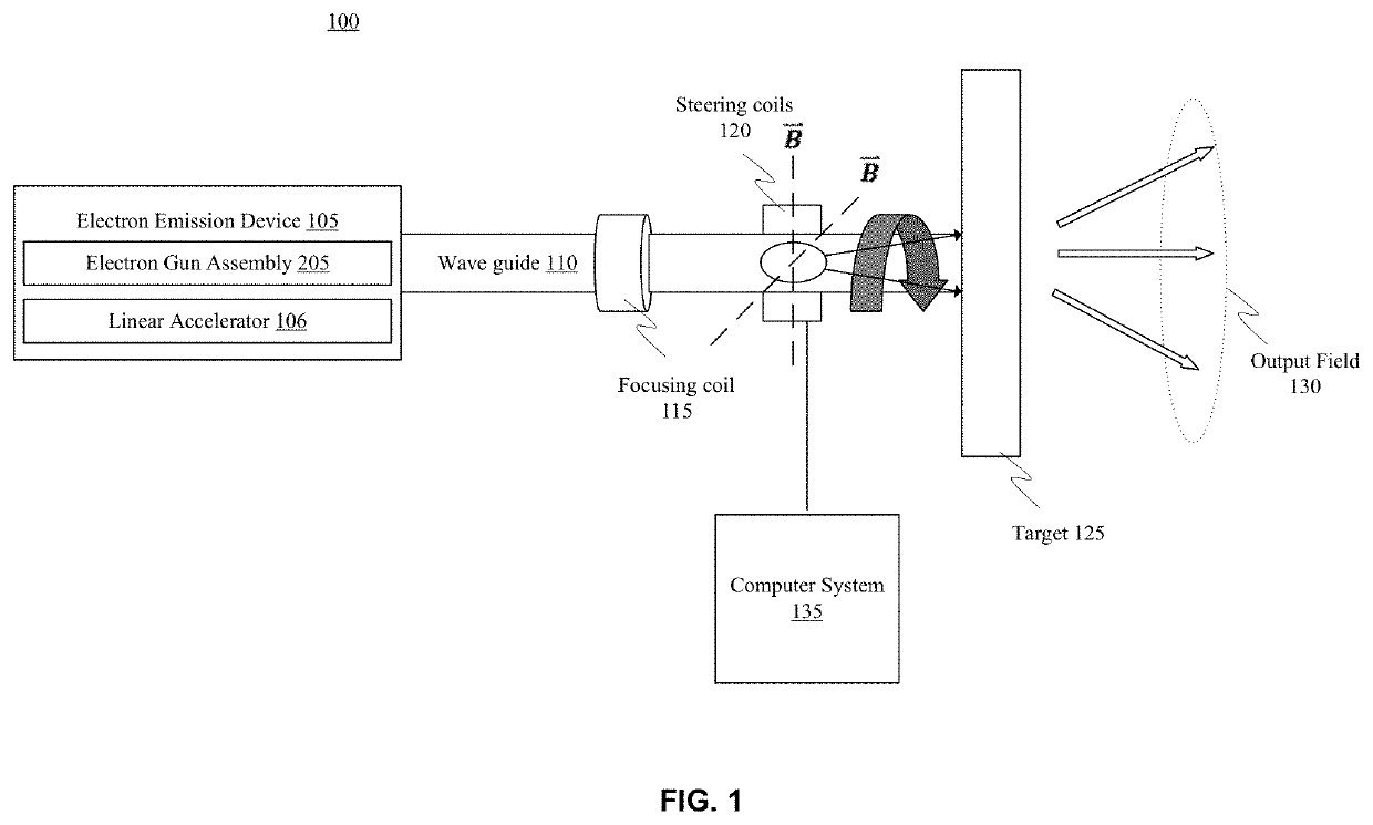
[0007]Embodiments of the present invention describe systems and methods for providing radiotherapy treatment by focusing an electron beam on a target (e.g., a tungsten plate) to produce a high-yield x-ray output with improved field shaping. A modified electron beam spatial distribution is employed to scan the target, for example, in a two-dimensional (2D) periodic path, which advantageously lowers the x-ray target temperature compared to the typical compact beam spatial distribution. As a result, the x-ray target can produce a high yield output without sacrificing the x-ray target life span. The use of a 2D periodic beam path allows a much colder target functioning regime such that more dosage can be applied in a short period of time compared to existing techniques.
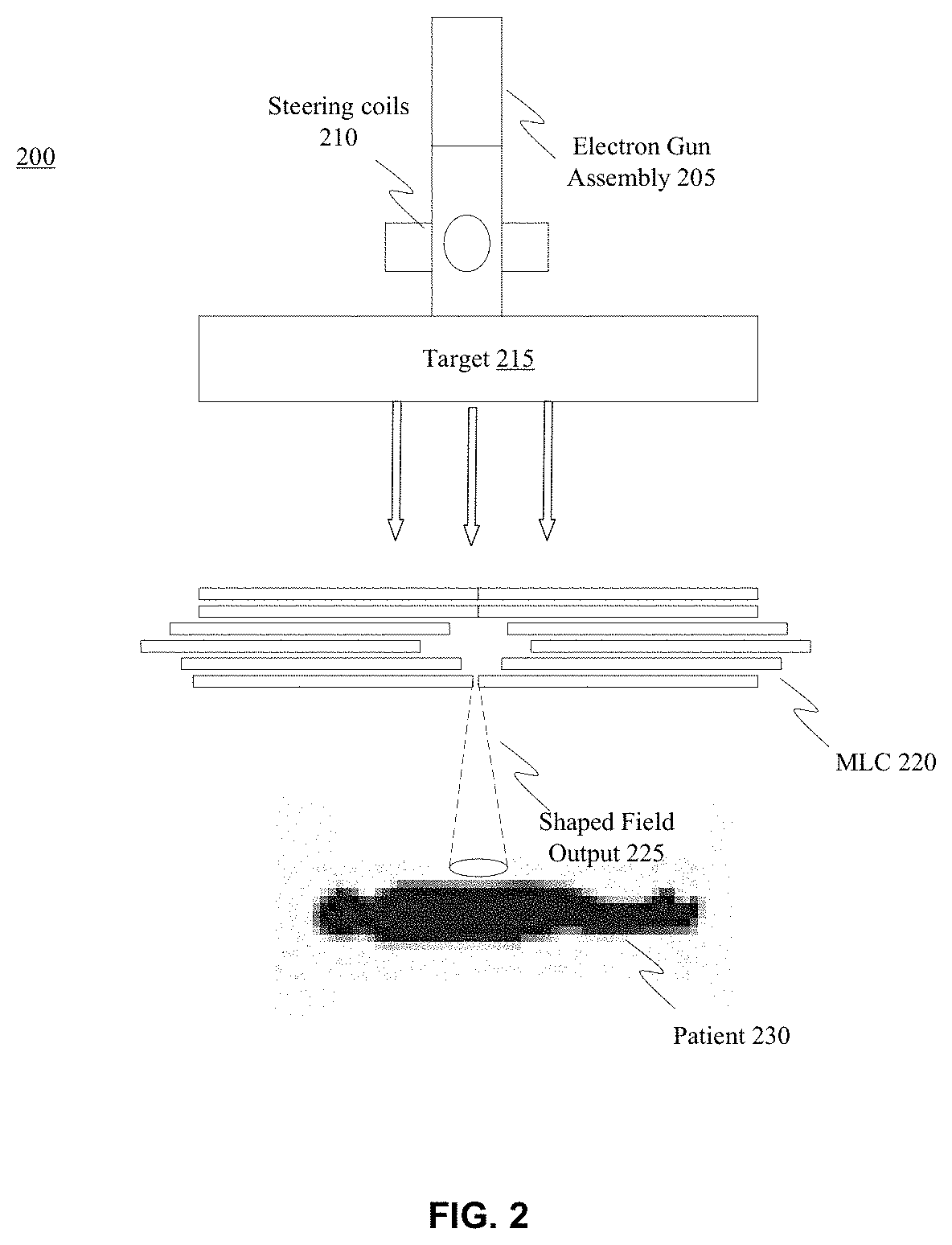
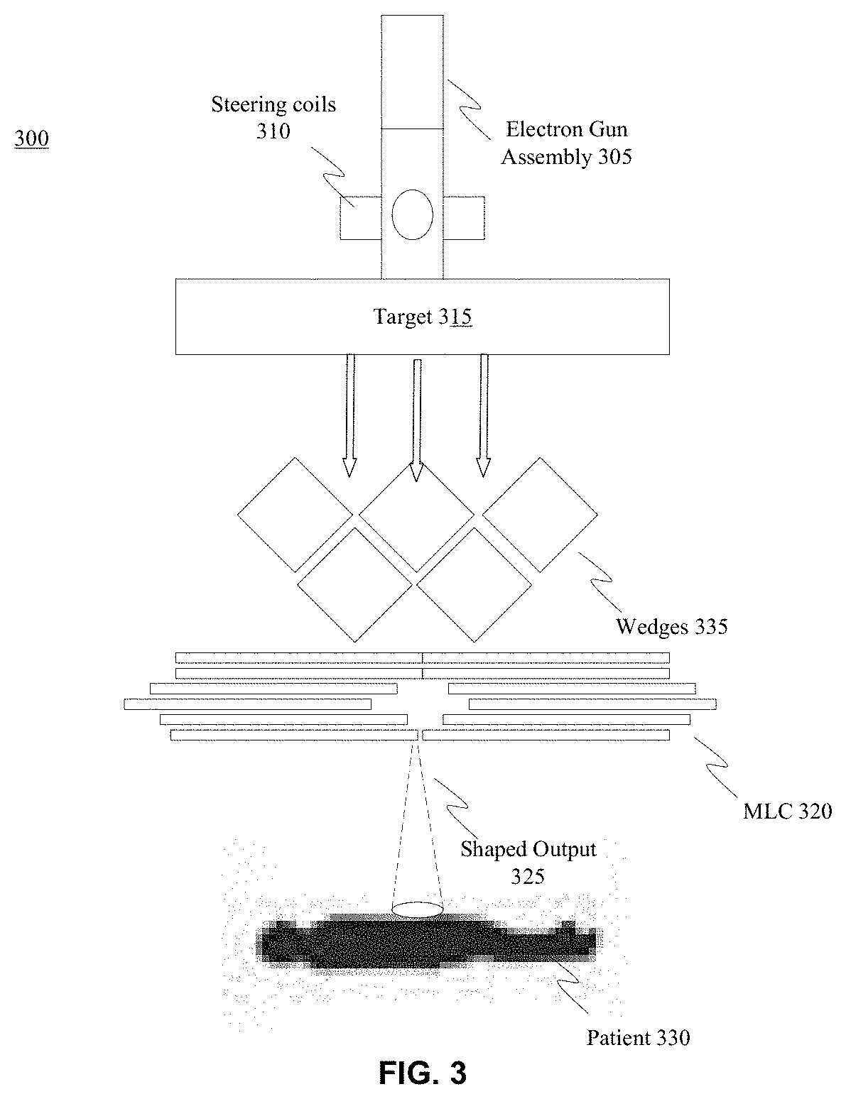
[0008]In addition to reducing heat concerns on the target, the annual beam distribution on the target creates x-ray fields can be used to provide custom dose applications to a patient where the dose applications can change shape and dose distribution much faster than would otherwise be provided or possible by use of a multileaf collimator. Therefore, embodiments of the present invention provide radiotherapy in faster durations, e.g., reduced treatment times. It is appreciated that multileaf collimators (and blocks) can be used in conjunction with the x-ray fields generated via the annual beam distribution of the present invention to further shape the dose application to the patient.

Problems solved by technology

The problem with using MLC as a field shaping device is that they are relatively slow to alter shape and therefore relatively slow to alter the field shape, e.g., the treatment volume, to the patient.

Method used


Image

  • Increased beam output and dynamic field shaping for radiotherapy system
  • Increased beam output and dynamic field shaping for radiotherapy system
  • Increased beam output and dynamic field shaping for radiotherapy system

Examples


Embodiment Construction

[0032]Reference will now be made in detail to several embodiments. While the subject matter will be described in conjunction with the alternative embodiments, it will be understood that they are not intended to limit the claimed subject matter to these embodiments. On the contrary, the claimed subject matter is intended to cover alternative, modifications, and equivalents, which may be included within the spirit and scope of the claimed subject matter as defined by the appended claims.

[0033]Furthermore, in the following detailed description, numerous specific details are set forth in order to provide a thorough understanding of the claimed subject matter. However, it will be recognized by one skilled in the art that embodiments may be practiced without these specific details or with equivalents thereof. In other instances, well-known methods, procedures, components, and circuits have not been described in detail as not to unnecessarily obscure aspects and features of the subject mat...


PUM


Abstract

Systems and methods provide radiotherapy treatment by focusing an electron beam on an x-ray target (e.g., a tungsten plate) to produce a high-yield x-ray output with improved field shaping. A modified electron beam spatial distribution is employed to scan the x-ray target, such as a 2D periodic beam path, which advantageously lowers the x-ray target temperature compared to the typical compact beam spatial distribution. As a result, the x-ray target can produce a high yield output without sacrificing the x-ray target life span. The use of a 2D periodic beam path allows a much colder x-ray target functioning regime such that more dosage can be applied in a short period of time compared to existing techniques.

Description

REFERENCE TO RELATED APPLICATIONS[0001]This application is a continuation of application Ser. No. 16 / 193,794 filed Nov. 16, 2018, entitled “Increased Beam Output and Dynamic Field Shaping for Radiotherapy System,” by Anuj Purwar et al., which claims the benefit of U.S. Provisional patent Application No. 62 / 587,331 filed Nov. 16, 2017, entitled “Increased Beam Output and Dynamic Field Shaping,” by Anuj Purwar et al., both of which are hereby incorporated herein by reference.FIELD[0002]Embodiments of the present invention generally relate to the field of radiotherapy. More specifically, embodiments of the present invention relate to techniques for increasing and shaping the beam output of radiotherapy systems.BACKGROUND[0003]A basic goal of radiotherapy treatment is the irradiation of a target volume while minimizing the amount of radiation absorbed in healthy tissue. Shaping the electron beam is an important way of minimizing the absorbed dose in healthy tissue and critical structure...

Claims


Application Information

Patent Timeline
Patent Type & Authority Applications(United States)
IPC IPC(8): A61N5/10H01J35/08H01J35/14
CPCA61N5/1044A61N5/1045A61N5/1077A61N5/1043H01J35/116A61N2005/1095A61N5/10A61N5/1042A61N5/1047A61N2005/1074A61N2005/1089H01J35/14A61N5/103A61N5/1082A61N5/1067A61N5/1078A61N2005/1092A61N5/1064A61N5/1065A61N5/1081
Inventor PURWAR, ANUJCONSTANTIN, DRAGOSCLAYTON, JAMES
Owner VARIAN MEDICAL SYSTEMS
Why Eureka
Try Eureka