
Force based digitization for bone registration

Pending Publication Date: 2021-08-26
THINK SURGICAL
View PDF0 Cites 0 Cited by
  • Summary
  • Abstract
  • Description
  • Claims
  • Application Information

AI Technical Summary

Benefits of technology

The patent describes a method and computer-assisted surgical system for determining the position and orientation of a patient's bone. The method involves using a digitizer tip to collect surface points on the bone and monitoring the forces exerted on the digitizer tip. When a threshold force is exceeded, the digitizer tip is removed to reduce the force. The system includes anatomy imaging data and digitizer tip position data to accurately locate the bone. The method and system provide a reliable and precise way to prepare for surgery and improve the accuracy of bone replacement and repair.

Problems solved by technology

Throughout a lifetime, bones and joints become damaged and worn through normal use, disease, and traumatic events.
Arthritis is a leading cause of joint damage, which can cause cartilage degradation, pain, swelling, stiffness, and bone loss overtime.
Even a slight misalignment of an implant may result in poor wear characteristics, reduced functionality, poor clinical outcomes, decreased implant longevity, or a combination of these outcomes.
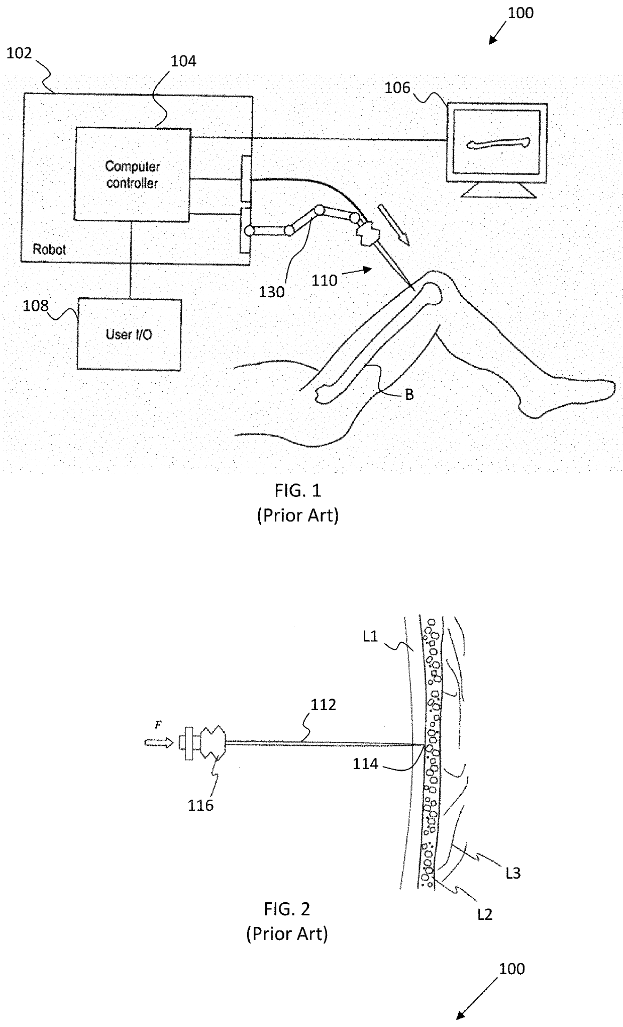
In practice, puncturing of the skin is desirable in some cases so as to reduce the size of the incision made in the patient; but also, it can be challenging to accurately digitize the bony surface through puncturing of the skin and tissue because the “view” is very limited and the tactile feedback is often compromised by the skin, muscle and periosteum.
Furthermore, a problem may arise during the bone digitizing process in an OR since the bone is covered in soft tissues, it is possible that the surgeon does not pierce through the soft tissue, such as cartilage to actually make contact with the cortex / outer surface of the bone.
Thus, while surgeons are required to penetrate through the cartilage and touch the underlying bone before picking a point for registration, failure to transit through the cartilage to the underlying bone still occurs and results in a failed registration procedure or worse, successful registration but misplaced implants.

Method used


Image

  • Force based digitization for bone registration
  • Force based digitization for bone registration
  • Force based digitization for bone registration

Examples


Embodiment Construction

[0032]The present invention has utility as a system and method for improving the accuracy of registering the position and orientation (POSE) of a bone during a surgical procedure. The present invention will now be described with reference to the following embodiments. As is apparent by these descriptions, this invention can be embodied in different forms and should not be construed as limited to the embodiments set forth herein. Rather, these embodiments are provided so that this disclosure will be thorough and complete, and will fully convey the scope of the invention to those skilled in the art. For example, features illustrated with respect to one embodiment can be incorporated into other embodiments, and features illustrated with respect to a particular embodiment may be deleted from the embodiment. In addition, numerous variations and additions to the embodiments suggested herein will be apparent to those skilled in the art in light of the instant disclosure, which do not depar...


PUM


Abstract

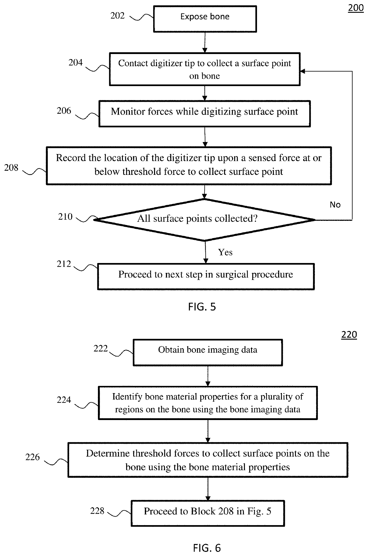
A method and system is provided for registering the position and orientation (POSE) of a bone, where only data points that rest on the cortex of the bone are used to establish data points for determining the bone's POSE during a surgical procedure. The method collects the contact force and only collects a data point upon the removal at a specific threshold, which allows a digitizer to pass through the cartilage or soft tissue prior to the condition which defines when a data collection switch is closed. The collection of points is more consistent since the threshold value is normalized to hounds-field units of computed tomography (CT) data used for segmentation. The method utilizes a load cell to define a selection of a point based upon the release of what the point load applied is, as well as normalizing the activation threshold to the CT data of the bone.

Description

CROSS REFERENCE TO RELATED APPLICATIONS[0001]This application claims priority benefit of U.S. Provisional Application Ser. No. 62 / 981,746 filed 26 Feb. 2020, the contents of which are hereby incorporated by reference.TECHNICAL FIELD[0002]The present invention generally relates to computer-assisted surgery, and in particular to systems and methods for registering a bone during computer-assisted surgery.BACKGROUND[0003]Throughout a lifetime, bones and joints become damaged and worn through normal use, disease, and traumatic events. Arthritis is a leading cause of joint damage, which can cause cartilage degradation, pain, swelling, stiffness, and bone loss overtime. If the pain associated with the dysfunctional joint is not alleviated by less-invasive therapies, the joint may need to be replaced with a procedure called total joint arthroplasty (TJR). TJR is an orthopedic surgical procedure in which the typically worn articular surfaces of the joint are replaced with prosthetic componen...

Claims


Application Information

Patent Timeline
IPC IPC(8): A61B34/20A61B5/00A61B6/00A61B90/50A61B34/30A61B17/56G16H40/67G16H30/40G16H50/70G16H20/40G16H50/50
CPCA61B34/20A61B6/032A61B5/4887A61B6/505A61B5/7203A61B5/7246A61B90/50A61B34/30A61B5/742A61B17/56G16H40/67G16H30/40G16H50/70G16H20/40G16H50/50A61B5/0053A61B2034/105A61B2034/2055A61B2090/065A61B2034/2068A61B2034/2059A61B6/035A61B6/5247G16H50/20A61B2017/564A61B2505/05A61B2562/0252A61B2562/0261
Inventor FORSTEIN, MICAHZUHARS, JOELFELENC, EUSTACHE
Owner THINK SURGICAL
Learn More