

Electrochromic material and method of manufacturing thereof
a technology of electrochromic materials and electrodes, applied in the field of electrochromic materials, can solve the problems of inability to provide a neutral color at colored and bleached states, inapplicability, and inability to provide any selection of available colors in art technology, etc., to achieve stable electrochemical characteristics, long life, and fast switching
- Summary
- Abstract
- Description
- Claims
- Application Information
AI Technical Summary
Benefits of technology
Problems solved by technology
Method used
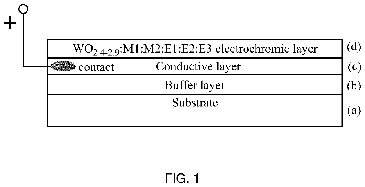
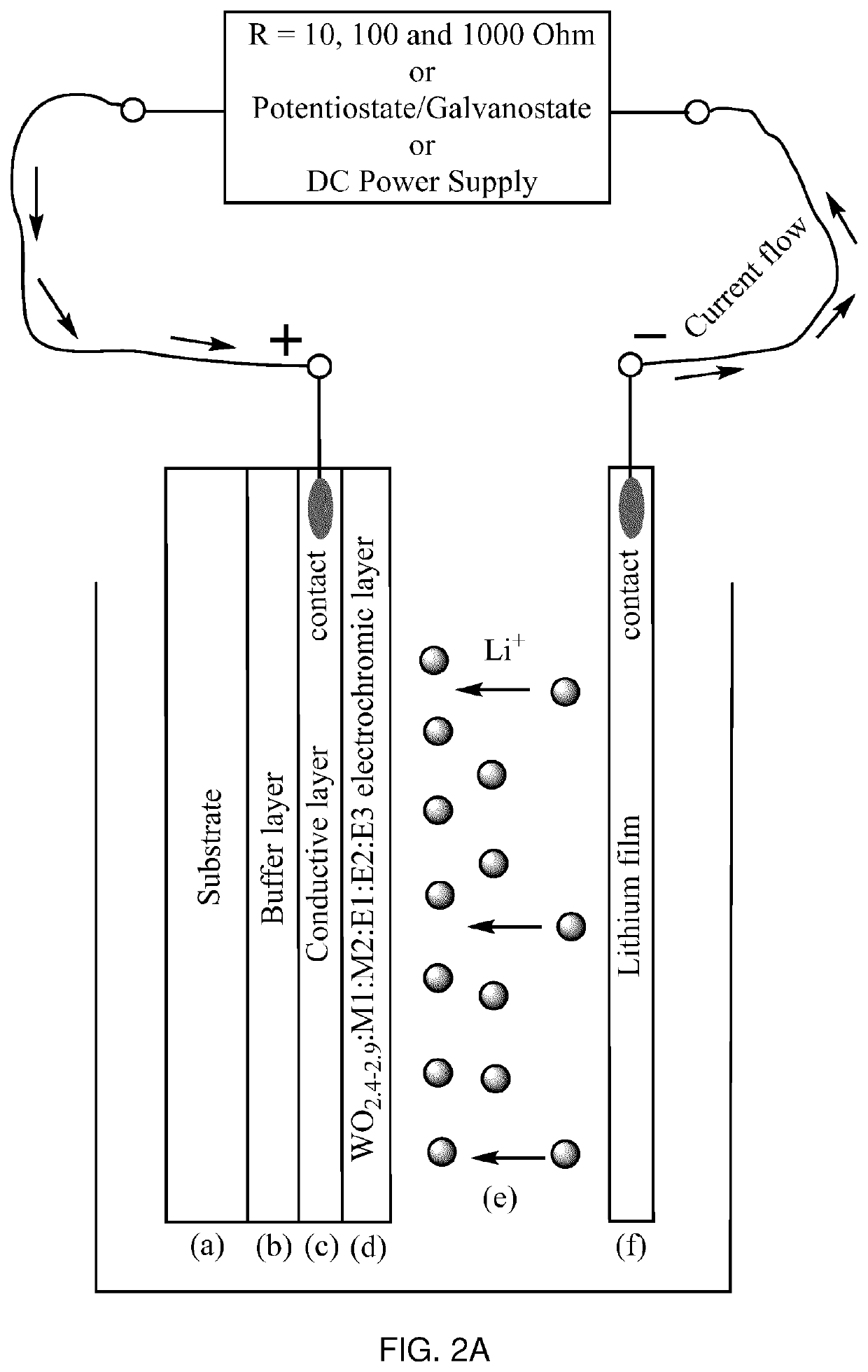
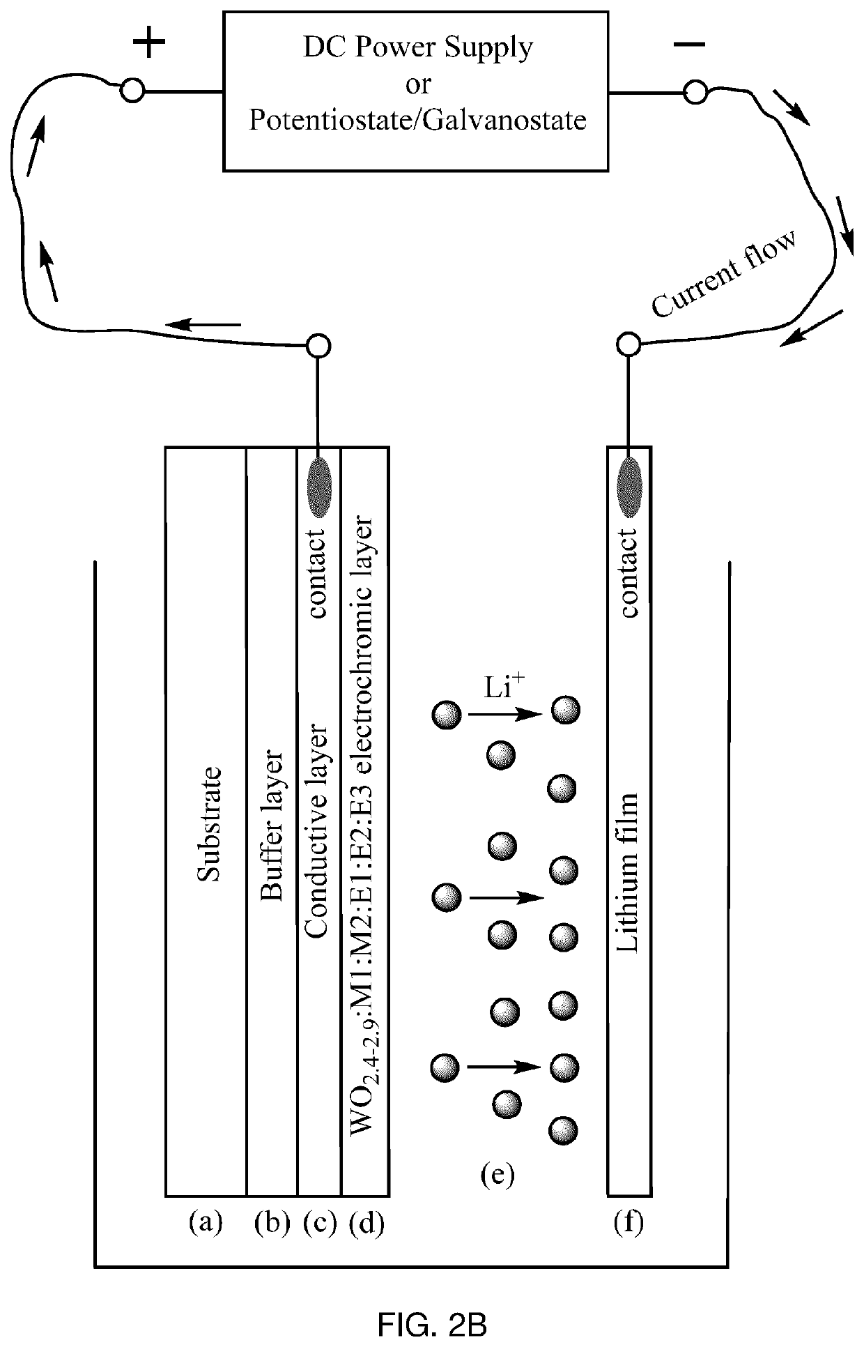
Image

Examples
example 1
[0104]W0.89O2.6:Al0.39:C0.02:N0.01 cathode EC material was synthesized from three targets, W, Al and Graphite, in Ar / O2 / N2 atmosphere by PDC reactive magnetron co-sputtering onto a Glass / FTO substrate at a room temperature. The thickness of the EC layer was 500-1000 nm. Sputtering pressure was 10 mT, and total gas flow was 80 seem with 6 sccm of O2 and 24 sccm of N2. Post-annealing was performed in a muffle oven at 500° C. in air atmosphere. Optical, electrochemical and dynamic switching measurements were performed in a liquid cell. The obtained EC material had deep blue color in the colored state and showed excellent switching time in PC—LiClO4 electrolyte (approximately 20-60 seconds for both colored and uncolored states) at 1.0-2.0 V using LiFePO4 as a counter electrode. Maximum transmittance of the film in the visible range was approximately 76% in the uncolored state and less than 0.3% in the colored state. There was no residual blue color after Li+ deintercalation in the uncol...
example 2
[0105]W0.9O2.6:Cr0.22:C0.12:N0.01 cathode EC material was synthesized from two targets, W and CrC, in Ar / O2 / N2 atmosphere by PDC reactive magnetron co-sputtering onto a Glass / FTO substrate at a room temperature. Thickness of the EC layer was 350-1000 nm. Sputtering pressure was 10 mT, and total gas flow was 80 sccm with 24 sccm of O2 and 6 sccm of N2. Post-annealing was performed in a muffle oven at 450° C. in air atmosphere. Optical, electrochemical and dynamic switching measurements were performed in a liquid cell. The obtained EC material had graphite-grey color in the colored state and showed an excellent switching time in PC—LiClO4 electrolyte (approximately 20-30 seconds for both colored and uncolored states) at 2.0 V with LiFePO4 counter electrode. Maximum transmittance in the visible range was approximately 71% in the uncolored state and less than 4% in the colored state. The sputtered film had a tiny brown tint after post-annealing (in the uncolored state) and this tint bec...
example 3
[0106]W0.9O2.6:Cr0.23:C0.14:H0.01:N0.01 cathode EC material was synthesized from three targets, W, Cr and Graphite, in Ar / CH4 / N2 / O2 atmosphere by PDC reactive magnetron co-sputtering onto a Glass / FTO substrate at a room temperature. Thickness of the EC layer was 350-1000 nm. Sputtering pressure was 10 mT, and total gas flow was 80 sccm with 24 sccm of O2 and 6 sccm of N2. Post-annealing was performed in a muffle oven at 450° C. in air atmosphere. Optical, electrochemical and dynamic switching measurements were performed in a liquid cell. The obtained EC material had almost black color in the colored state and still showed a good switching time in PC—LiClO4 electrolyte (approximately 60 seconds for the colored state and 90 seconds for the uncolored state) at 2.0V with LiFePO4 counter electrode. Maximum transmittance in the visible range was approximately 65% in the uncolored state and less than 1% in the colored state. The sputtered film had a brown tint after post-annealing (in the ...
PUM
| Property | Measurement | Unit |
|---|---|---|
| temperature | aaaaa | aaaaa |
| temperature | aaaaa | aaaaa |
| temperature | aaaaa | aaaaa |
Abstract
Description
Claims
Application Information