
Apparatus comprising a support system for a user and its operation in a gravity-assist mode

a technology of support system and user, which is applied in the field of apparatus comprising a support system for a user and its operation in a gravity-assist mode, can solve the problems of neurologically impaired individuals imposing challenging conditions, affecting the function of the apparatus, and affecting the ability of the apparatus to perform normal activities, so as to promote activity-dependent neuroplasticity and motor recovery, and minimize the mechanical impact of the trunk suppor

Inactive Publication Date: 2021-09-16
ECOLE POLYTECHNIQUE FEDERALE DE LAUSANNE (EPFL)
View PDF0 Cites 2 Cited by
  • Summary
  • Abstract
  • Description
  • Claims
  • Application Information

AI Technical Summary

Benefits of technology

The patent describes a technology that helps individuals with spinal cord injuries or strokes walk and run more confidently and comfortably. This technology uses a robot to provide assistance and allows for more natural and skilled locomotion. The robot can also be used in a virtual or augmented reality program to make training more interesting and rewarding for the individual. The technology is based on precise trunk assistance and active participation, and it can be used in a gait rehabilitation program to restore motor control. The robot is controlled by epidural electrical stimulation over the spinal cord, which allows for individualized training and recovery of motor function. Overall, this technology can improve the quality of life for individuals with mobility issues and make rehabilitation more effective.

Problems solved by technology

However, the locomotor impairments resulting from neurological insults such as spinal cord injury (SCI) and stroke stress out the instability of the human gait and the complexity of its neural control.
These approaches suffer from several drawbacks.
First, continuous treadmill belt motion dictates the pace of locomotor movements, imposing challenging conditions for neurologically impaired individuals who exhibit variable gait patterns (14).
Second, treadmill-restricted environments markedly differ from the rich repertoire of natural locomotor activities underlying daily living.
Third, vertically restricted trunk support creates undesired anteroposterior and lateral forces that impede gait execution (17, 18).
Testing robotic systems in quadrupedal animal model poses further problems.
In contrast, the application of forces to the trunk in the bipedal posture of humans is likely to exert additional and specific constraints.

Method used


Image

  • Apparatus comprising a support system for a user and its operation in a gravity-assist mode
  • Apparatus comprising a support system for a user and its operation in a gravity-assist mode
  • Apparatus comprising a support system for a user and its operation in a gravity-assist mode

Examples


example 1

Experimental Protocol 1: Properties and Validation of the Neurorobotic Platform

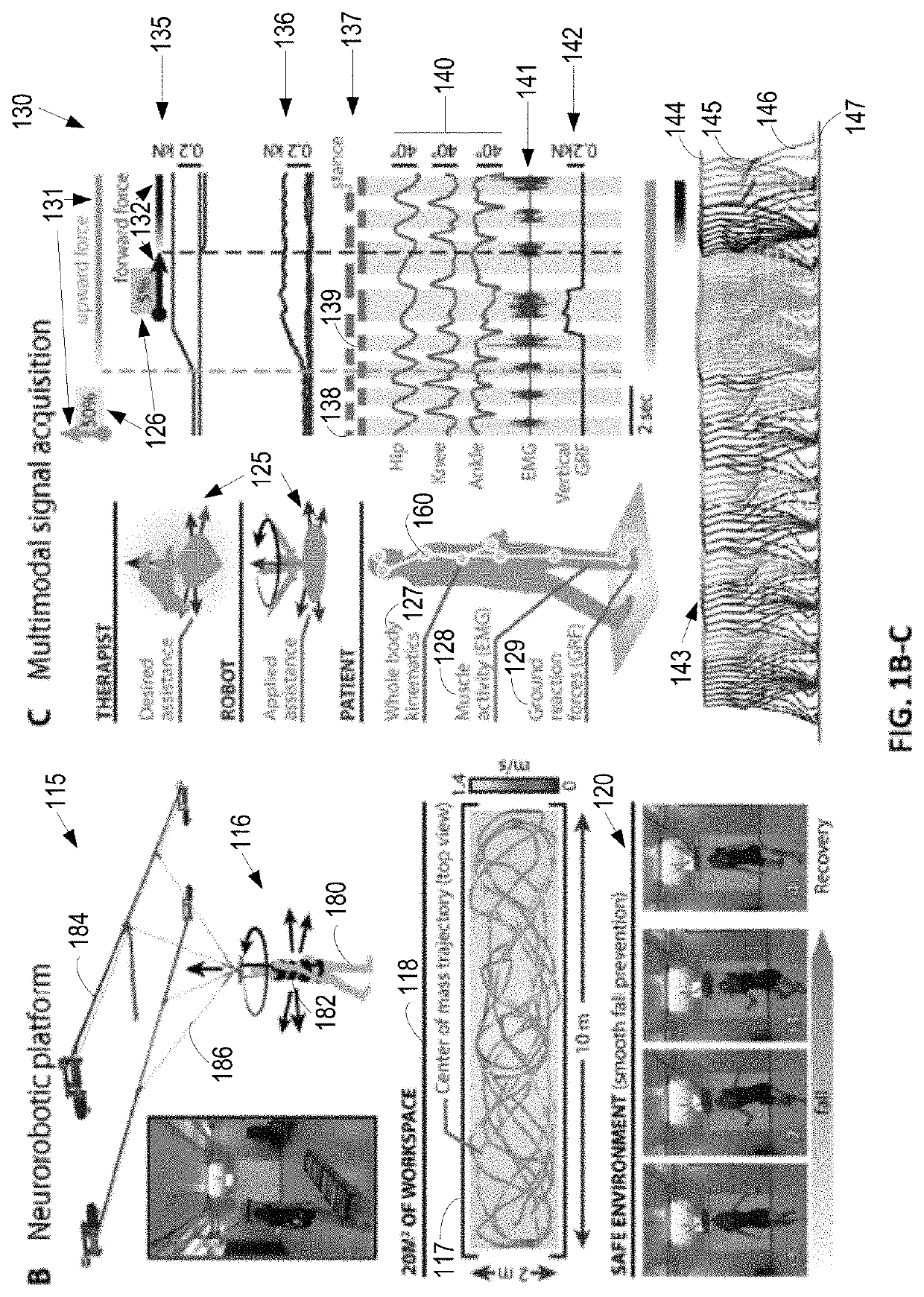
[0322]Eight healthy subjects were recorded during locomotion without and with robot along a straight or curvilinear path projected on the floor using the augmented reality system. They were asked to walk naturally at their own selected pace. They wore the harness during both conditions. The robot was configured in transparent mode, which corresponds to the minimal upward force (4 kg) necessary to enable robot-subject interactions. For each condition, a total of 10 steady-state gait cycles were recorded and analyzed.

example 2

Experimental Protocol 2: Impact of Upward and Forward Forces on Posture and Gait

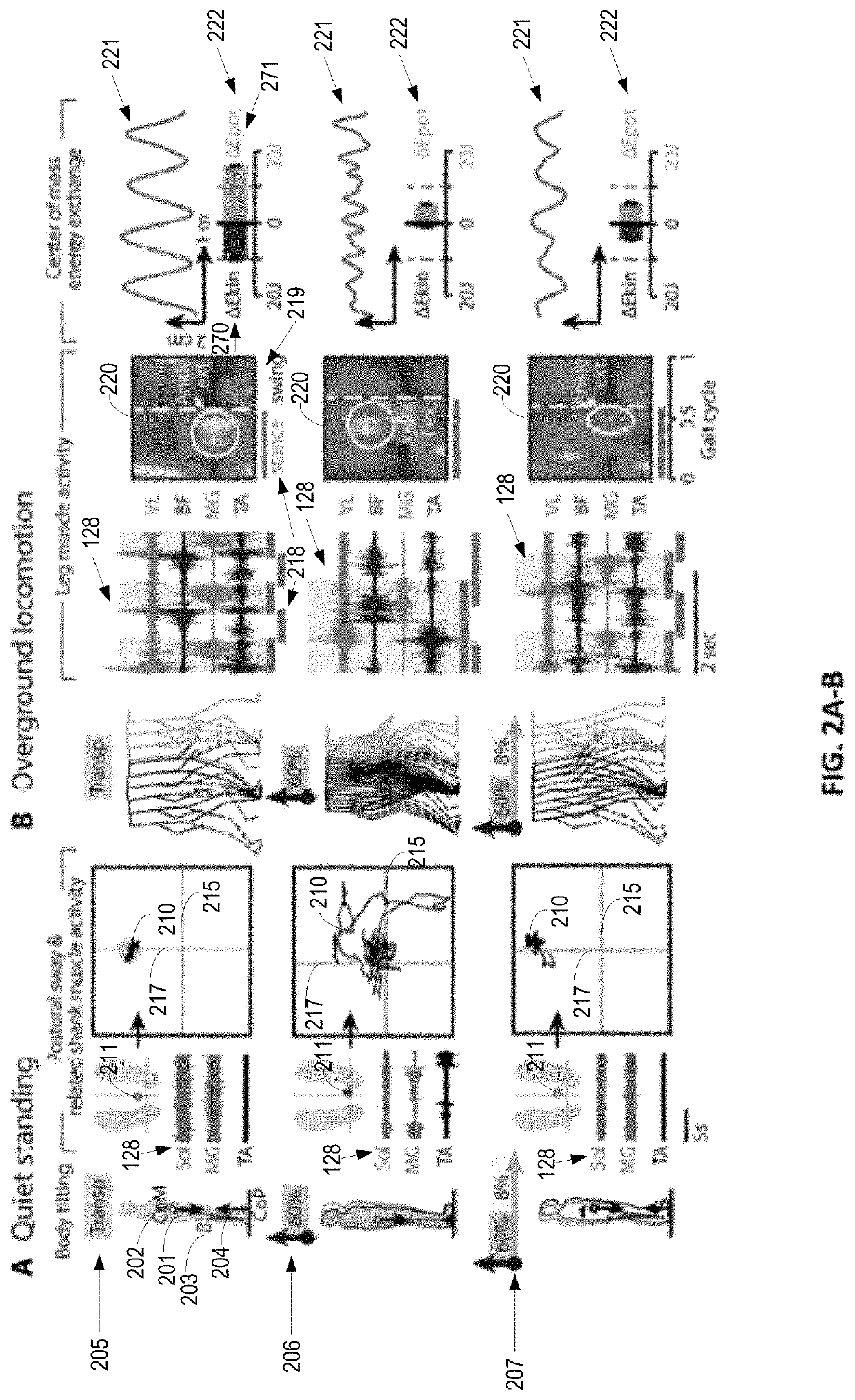
[0323]Five subjects were first recorded during quiet standing while attached to the robotic interface. They were asked to stand quietly with eyes open. Each foot was positioned on its own force plate with a standardized location and orientation (58). The distance between the medial side of the heels was set at 8.4 cm and the external rotation angle of the feet was kept at 9 deg with respect to the sagittal plane. The subjects were instructed to center and stabilize their center of foot pressure that was projected on the floor in real-time through the augmented reality system. This visual biofeedback was removed during recordings. The subjects were then asked to stare at a visual reference mark projected on the floor 3 m straight ahead in front of them. Each trial lasted 20 seconds. Two trials were collected for each upward and forward force.

[0324]The same subjects were then evaluated during locomotion ac...

example 3

Experimental Protocol 3: Design of Gravity-Assist Algorithm: Personalization of Upward Force

[0325]Nine subjects with a SCI or a stroke were tested during quiet standing over the maximum possible range of upward forces under the same conditions as explained in Experimental Protocol 2. For each upward force, two trials were collected that each lasted 20 s and were separated by 1 min. Each trial was then divided into a set of 20 windows of 1 s over which 15 kinematic, kinetic and electromyographic parameters were computed. A PC analysis was applied on these variables to determine the optimal upward force for each subject.

[0326]The this dataset and results were used to build an artificial neural network that calculated the necessary correction of upward force to provide each subject with optimal upward force. The artificial neural network integrated the kinematic and kinetic parameters (n=12, 10 seconds of recording). 13 learning rules and 11 structures were tested with different number...


PUM


Abstract

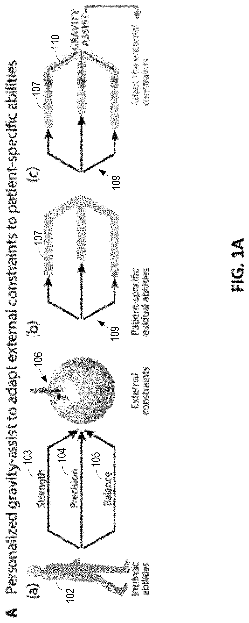
The present application relates to devices and systems for rehabilitation of the locomotor system, for example limbs. In particular, the present application discloses an apparatus, more in particular a robotic platform capable of optimizing gravity-dependent trunk movements, enabling overground locomotion in non-ambulatory individuals with spinal cord injury and stroke, while promoting durable motor improvement when delivered during gait rehabilitation facilitated by electrical spinal cord stimulation.

Description

[0001]The present application relates to the field of locomotion control and medical engineering, and in some examples to devices, methods and / or systems for rehabilitation of subjects with neurological disorders, such as the rehabilitation of the locomotor system, including limbs. In one example, the present application discloses an apparatus, more in particular a robotic platform capable of optimizing gravity-dependent trunk movements, enabling overground locomotion in non-ambulatory individuals with spinal cord injury and stroke, while promoting durable motor improvement when delivered during gait rehabilitation facilitated by electrical spinal cord stimulation.BACKGROUND AND SUMMARY[0002]Gait recovery after neurological disorders requires re-mastering the interplay between body mechanics and gravitational forces. Despite the importance of gravity-dependent gait interactions and active participation for promoting this learning, these essential components of gait rehabilitation ha...

Claims


Application Information

Patent Timeline
IPC IPC(8): A61H3/00A61N1/05A61N1/36B25J9/00
CPCA61H3/00A61N1/0551A61N1/36003A61N1/36067B25J9/0006A61H2201/10A61H2201/1666A61H2201/5007A61H2201/5061A61H2201/5069A61H2201/165A61B5/7282A63B69/0064A61H3/008A61B5/112A61B5/1121A63B24/0087A61B2562/0219A61B2562/0247A63B2213/004A63B2220/10A63B2220/51A63B22/0235A63B2220/805A63B2220/806A63B2230/60A61B5/389A61B5/395
Inventor VON ZITZEWITZ, JOACHIMMIGNARDOT, JEAN BAPTISTELE GOFF, CAMILLE GEORGETTE MARIECOURTINE, GRÉGOIREVALLERY, HEIKEPLOOIJ, MICHIEL
Owner ECOLE POLYTECHNIQUE FEDERALE DE LAUSANNE (EPFL)
Learn More