Supercharge Your Innovation With Domain-Expert AI Agents!

Magnetoacoustic emission detection method for fatigue damage of ferromagnetic metal component

a technology of ferromagnetic metal and emission detection, which is applied in the direction of material magnetic variables, instruments, and processing of detected response signals, can solve the problems of inability to distinguish failure of components often occurring quickly, and inability to detect the steady expansion stage of fatigue cracks. the effect of improving the anti-noise capacity of mae and stable and reliable detection results

Active Publication Date: 2021-12-02
CHINA SPECIAL EQUIP INSPECTION & RES INST
View PDF3 Cites 2 Cited by
  • Summary
  • Abstract
  • Description
  • Claims
  • Application Information

AI Technical Summary

Benefits of technology

The present patent has two main benefits compared to previous practices. The first effect is that the use of a square wave voltage signal as an excitation signal, based on a reference voltage adjusted by a sine wave, allows for the identification of the development inflexion point of stable expansion and rapid expansion of fatigue microckets, which can give a timely early warning for the failure of components. The second effect is that the use of a square wave voltage signal as the excitation signal provides a better anti-noise capacity, resulting in more accurate and reliable fatigue monitoring, with a stable and reliable detection result.

Problems solved by technology

Once the rapid fatigue crack expansion stage II appears, the failure of components often occurs quickly.
Traditional nondestructive testing techniques, such as magnetic powder, eddy current and permeation, can only detect macroscopic or visible fatigue cracks, that is, fatigue cracks in stage II rapidly expanded to cracks with a certain length.
However, it cannot distinguish the fatigue crack steady expansion stage I from the rapid expansion stage II.
The change of fatigue microcrack expansion cannot be identified, thus failing to give an early warning to component failure.
The common signal is a hump envelope or an envelope overlap, and the root mean square voltage of the signal is greatly affected by the environment, so that it is difficult to ensure the reliability and accuracy of judging and identifying fatigue damage based on this characteristic parameter.

Method used


Image

  • Magnetoacoustic emission detection method for fatigue damage of ferromagnetic metal component
  • Magnetoacoustic emission detection method for fatigue damage of ferromagnetic metal component
  • Magnetoacoustic emission detection method for fatigue damage of ferromagnetic metal component

Examples


Embodiment Construction

[0032]The present disclosure will be further explained with reference to the attached drawings and specific embodiments.

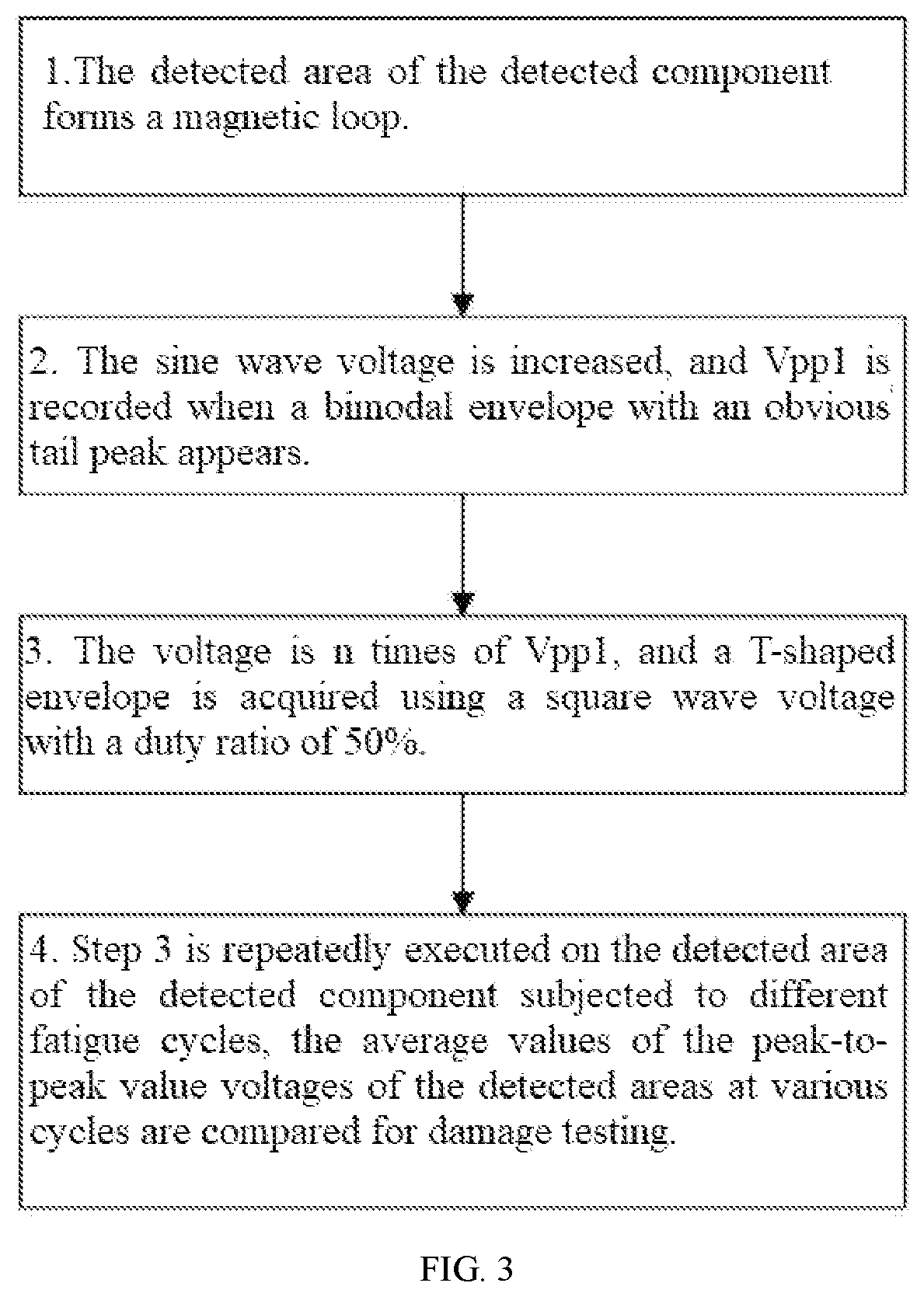
[0033]Refer to FIG. 3 for the block diagram of the steps of the detection method according to the present disclosure. The steps are as follows.

[0034]1) The self-made U-shaped electromagnetic yoke and the acoustic emission sensor are placed in a relatively fixed position in the central area of Q235 steel components without being subjected to fatigue loading.

[0035]2) A periodic sine wave voltage signal is loaded to the coil of the U-shaped electromagnetic yoke. The frequency of the signal is 20 Hz, wherein the voltage signal is generated by a function generator, amplified by a power amplifier 10 times and then input to the coil. Because MAE signals are generated under the alternating magnetic field excited by sine wave voltage signals, Q235 steel components generate two identical MAE signals in one magnetization cycle, that is, the frequency of MAE signals is twice t...


PUM

PropertyMeasurementUnit
frequencyaaaaaaaaaa
frequencyaaaaaaaaaa
magnetizationaaaaaaaaaa

Abstract

A magneto acoustic emission detection method for fatigue damage of ferromagnetic metal components: First, generating an excitation magnetic field by using a sine wave voltage signal, gradually increasing a loading voltage until a magneto acoustic emission signal of a bimodal envelope with an obvious tail peak is acquired, and taking a corresponding voltage peak value as a reference voltage; second, generating an excitation magnetic field by using a square wave voltage signal equal to or higher than a reference voltage, and acquiring a magneto acoustic emission signal with a T-shaped envelope; and third, calculating the average value of peak-to-peak values of the magneto acoustic emission signal in multiple periods to serve as a characteristic parameter, and enabling the characteristic parameter to have inflection point change along with the development of the initiation and expansion of the fatigue crack, and giving a timely early warning for the failure of the component.

Description

CROSS REFERENCE TO RELATED APPLICATION(S)[0001]This patent application claims the benefit and priority of Chinese Patent Application No. 202010471484.3, filed on May 28, 2020, the disclosure of which is incorporated by reference herein in its entirety as part of the present application.TECHNICAL FIELD[0002]The present disclosure belongs to the technical field of nondestructive testing of material damage, and particularly relates to a magneto acoustic emission detection method for fatigue damage of ferromagnetic metal components.BACKGROUND ART[0003]The fatigue life of metal components subjected to cyclic loading for a long time can be divided into three stages: (1) the first stage is the fatigue hardening or softening stage, in which the microstructure of the material changes as a whole, eventually forming stress-strain concentration areas and resulting in fatigue damage; (2) the second stage is the crack initiation stage, in which the crack length is usually not larger than the grai...

Claims


Application Information

Patent Timeline
Patent Type & Authority Applications(United States)
IPC IPC(8): G01N27/72G01B7/24
CPCG01N27/725G01B7/24G01N29/14G01N29/2412G01N29/44G01N2291/0234G01N2291/0289
Inventor SHEN, GONGTIANSHEN, YONGNAZHANG, WENJUN
Owner CHINA SPECIAL EQUIP INSPECTION & RES INST
Features
  • R&D
  • Intellectual Property
  • Life Sciences
  • Materials
  • Tech Scout
  • Unparalleled Data Quality
  • Higher Quality Content
  • 60% Fewer Hallucinations
Learn More