
Conductive wire structure and manufacturing method thereof

a technology of conductive wires and manufacturing methods, applied in the direction of semiconductor devices, semiconductor/solid-state device details, electrical apparatus, etc., can solve the problems of short circuit, reducing the alignment margin between the contact and the conductive wire, etc., and achieve the effect of increasing the alignment margin

Active Publication Date: 2021-12-23
WINBOND ELECTRONICS CORP
View PDF0 Cites 0 Cited by
  • Summary
  • Abstract
  • Description
  • Claims
  • Application Information

AI Technical Summary

Benefits of technology

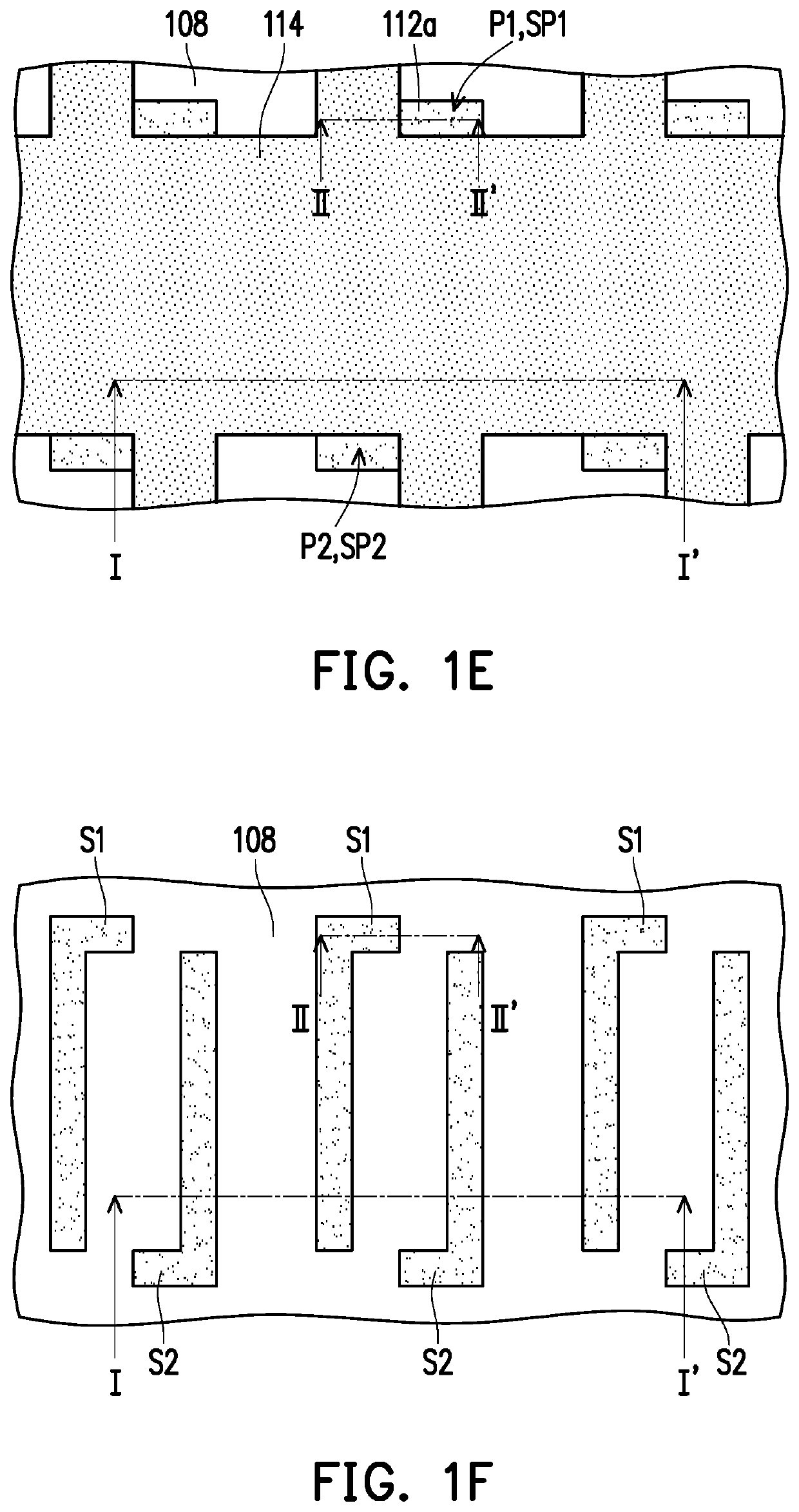
The invention provides a conductive wire structure and a manufacturing method that can increase the alignment margin between contacts and conductive wires, prevent short circuits between adjacent wires, and increase the area for electrically connecting with contacts. The method uses a simplified process, reducing complexity, and allows for flexible adjustment of the distance between wires. The structure has first and second conductive wires with separate pad portions that extend in different directions to prevent short circuits. These technical effects improve the reliability and efficiency of the conductive wire structure.

Problems solved by technology

When the critical dimension of the conductive wire is reduced, it will make it difficult to align the subsequently formed contact with the conductive wire, thereby reducing the alignment margin between the contact and the conductive wire.
In addition, when the distance between the conductive wires is shortened, the contact is easily connected to two adjacent conductive wires simultaneously to cause the problem of short circuit.

Method used


Image

  • Conductive wire structure and manufacturing method thereof
  • Conductive wire structure and manufacturing method thereof
  • Conductive wire structure and manufacturing method thereof

Examples


Embodiment Construction

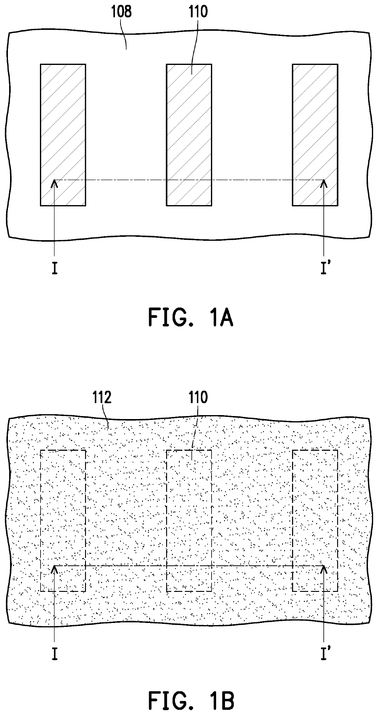
[0013]Referring to FIG. 1A and FIG. 2A, a substrate 100 is provided. The substrate 100 may be a semiconductor substrate, such as a silicon substrate. Furthermore, one of ordinary skill in the art may form a semiconductor device (e.g., a transistor) (not shown) and a dielectric layer (not shown) on the substrate 100 according to product requirements, and the description thereof is omitted herein.

[0014]A conductive layer 102 is formed on the substrate 100. The conductive layer 102 may be a single-layer structure or a multi-layer structure. For example, the conductive layer 102 may be a multilayer structure including a conductive layer 104 and a conductive layer 106, but the invention is not limited thereto. The conductive layer 104 is, for example, doped polysilicon. The conductive layer 106 is, for example, a metal or metal compound, such as tungsten, tungsten nitride, aluminum, titanium nitride, or copper.

[0015]A hard mask layer 108 may be formed on the conductive layer 102. The har...


PUM

PropertyMeasurementUnit
conductiveaaaaaaaaaa
lengthaaaaaaaaaa
widthaaaaaaaaaa

Abstract

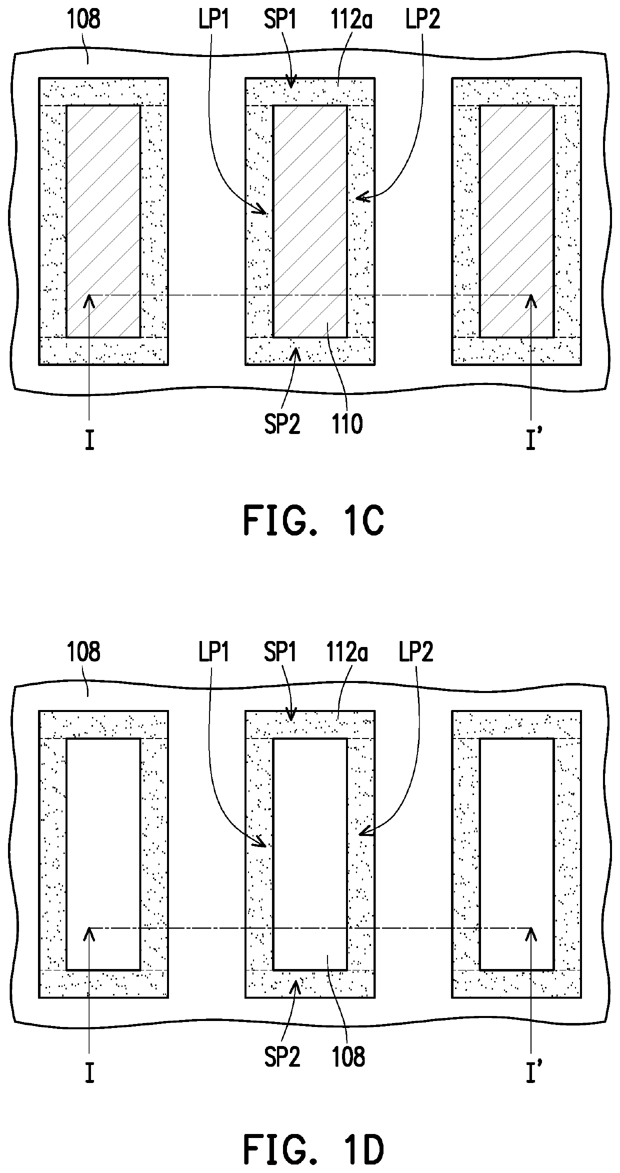
A method of manufacturing a conductive wire structure including following steps is provided. A conductive layer is formed on a substrate. A rectangular ring spacer is formed on the conductive layer by a self-aligned double patterning process. A patterned photoresist layer is formed. The patterned photoresist layer exposes a first portion and a second portion of the rectangular ring spacer. The first and second portions are located at two corners on a diagonal of the rectangular ring spacer. The first and second portions are removed by using the patterned photoresist layer as a mask to form a first spacer and a second spacer. The first spacer and the second spacer are L-shaped. The patterned photoresist layer is removed. A pattern of the first spacer and a pattern of the second spacer are transferred to the conductive layer to form an L-shaped first conductive wire and an L-shaped second conductive wire.

Description

BACKGROUND OF THE INVENTIONField of the Invention[0001]The invention relates to a semiconductor device and a manufacturing method thereof, and particularly relates to a conductive wire structure and a manufacturing method thereof.Description of Related Art[0002]With the advancement of semiconductor technology, the size of device has also continued to shrink. As the integrity of the integrated circuit increases, the critical dimension of the conductive wire and the distance between the conductive wires will decrease accordingly. When the critical dimension of the conductive wire is reduced, it will make it difficult to align the subsequently formed contact with the conductive wire, thereby reducing the alignment margin between the contact and the conductive wire. In addition, when the distance between the conductive wires is shortened, the contact is easily connected to two adjacent conductive wires simultaneously to cause the problem of short circuit.SUMMARY OF THE INVENTION[0003]Th...

Claims


Application Information

Patent Timeline
Patent Type & Authority Applications(United States)
IPC IPC(8): H01L21/3213H01L21/033H01L23/528
CPCH01L21/32139H01L23/528H01L21/0337H01L21/76885H01L23/5283H01L23/5226
Inventor CHEN, HUANG-NAN
Owner WINBOND ELECTRONICS CORP
Learn More