
System and process for electricity generation using steam production by hydrogen combustion

a technology of electricity generation and hydrogen combustion, which is applied in the direction of machines/engines, lighting and heating apparatus, energy input, etc., can solve the problems of limited wide implementation of renewable energy, inexpensive carbon-based fuels, and effectively with traditional fuels, so as to reduce co2 emissions and reduce emissions. , the effect of reducing the emission of co2

Active Publication Date: 2022-01-06
RUIZ ROBERTO
View PDF5 Cites 2 Cited by
  • Summary
  • Abstract
  • Description
  • Claims
  • Application Information

AI Technical Summary

Benefits of technology

The invention is about a system and process for generating electricity by using steam produced by hydrogen combustion. The system uses a Rankine Cycle system and a mixture of primary pure hydrogen fuel and secondary fuels like natural gas or methane to reduce emissions of CO2. The system also uses a flame temperature reducing fluid like flue gas recirculation, water injection, or steam injection to decrease CO2 emissions and increase equipment life. Overall, the system reduces emissions of CO2, NOx, and other greenhouse gases into the atmosphere and also decreases bulk flame temperatures to improve equipment efficiency and decrease failures.

Problems solved by technology

The availability of inexpensive carbon-based fuels, however, limited the wide implementation of renewable energy as it could not compete effectively with traditional fuels.
Government grants and subsidies for renewable energy sources helped maintain interest in research and development and electricity supply, but inroads in the overall energy market were modest at best.
Unfortunately, the inherent non-continuous supply of solar and wind power for electricity generation presents a challenge requiring carbon-based electricity generation for back-up supply when either the sun or wind are not available.
Currently, renewable energy plants stop generating electricity when the supply of solar or wind energy is unavailable.
However, the amount of energy they can store is typically only a few hours, making them an unreliable back-up system when the downtime exceeds more than four (4) hours.
In addition, the cost of lithium-ion batteries needs to come down for them to be more competitive as a storage option and the availability of battery materials could become a problem in the future as electric cars and residential energy storage gain popularity.
In addition, as batteries become more widespread, it cannot be discarded that some of the natural resources to manufacture them may not be sufficient to satisfy demand, as well as potential serious environmental concerns related to their disposal after their useful life.
However, broad implementation in large-scale electricity generation remains elusive due to scaling, high costs and reliability issues.
Although these approaches eliminate some CO2, they would generate very large amounts of highly regulated air polluting nitrogen oxides (NOx) which require post-combustion treatments such as Selective Catalytic Reduction (SCR) or Selective Non-Catalytic Reduction (SNCR).
Although both SCR and SNCR are utilized in many electricity generation and industrial applications, their use of ammonia (a toxic air pollutant), or other toxic reagents, combined with high capital and operating costs make them less-than-ideal solutions to meet environmental regulations.
Unfortunately, despite these efforts, the worldwide use of coal continues to grow.
In addition, higher adiabatic flame temperatures like those found in H2 combustion could shorten the life, or even create catastrophic failure, of metallic and ceramic components in burners, boilers, furnaces, heaters, etc.
However, these techniques have not been used to reduce bulk flame temperatures with the primary objective of maintaining equipment life or eliminating equipment failure.

Method used


Image

  • System and process for electricity generation using steam production by hydrogen combustion
  • System and process for electricity generation using steam production by hydrogen combustion
  • System and process for electricity generation using steam production by hydrogen combustion

Examples


Embodiment Construction

[0039]While this invention is susceptible of embodiment in many different forms, there is shown in the drawings, and will herein be described hereinafter in detail, some specific embodiments of the instant invention. It should be understood, however, that the present disclosure is to be considered an exemplification of the principles of the invention and is not intended to limit the invention to the specific embodiments so described.

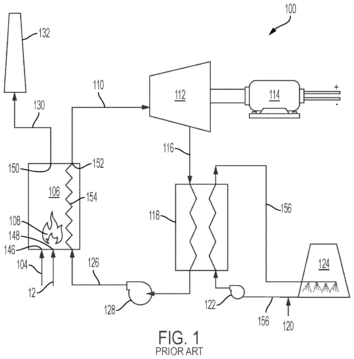
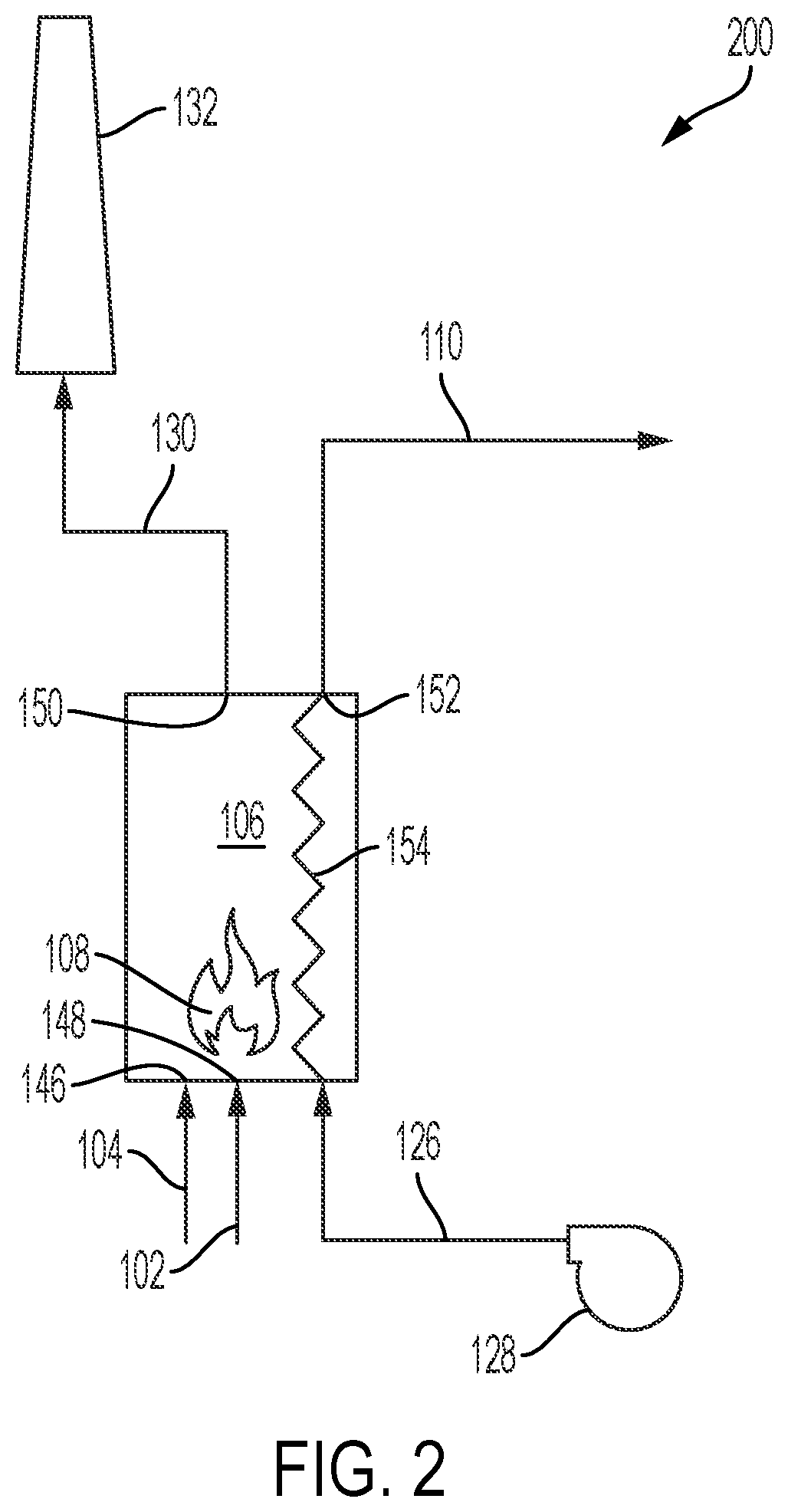
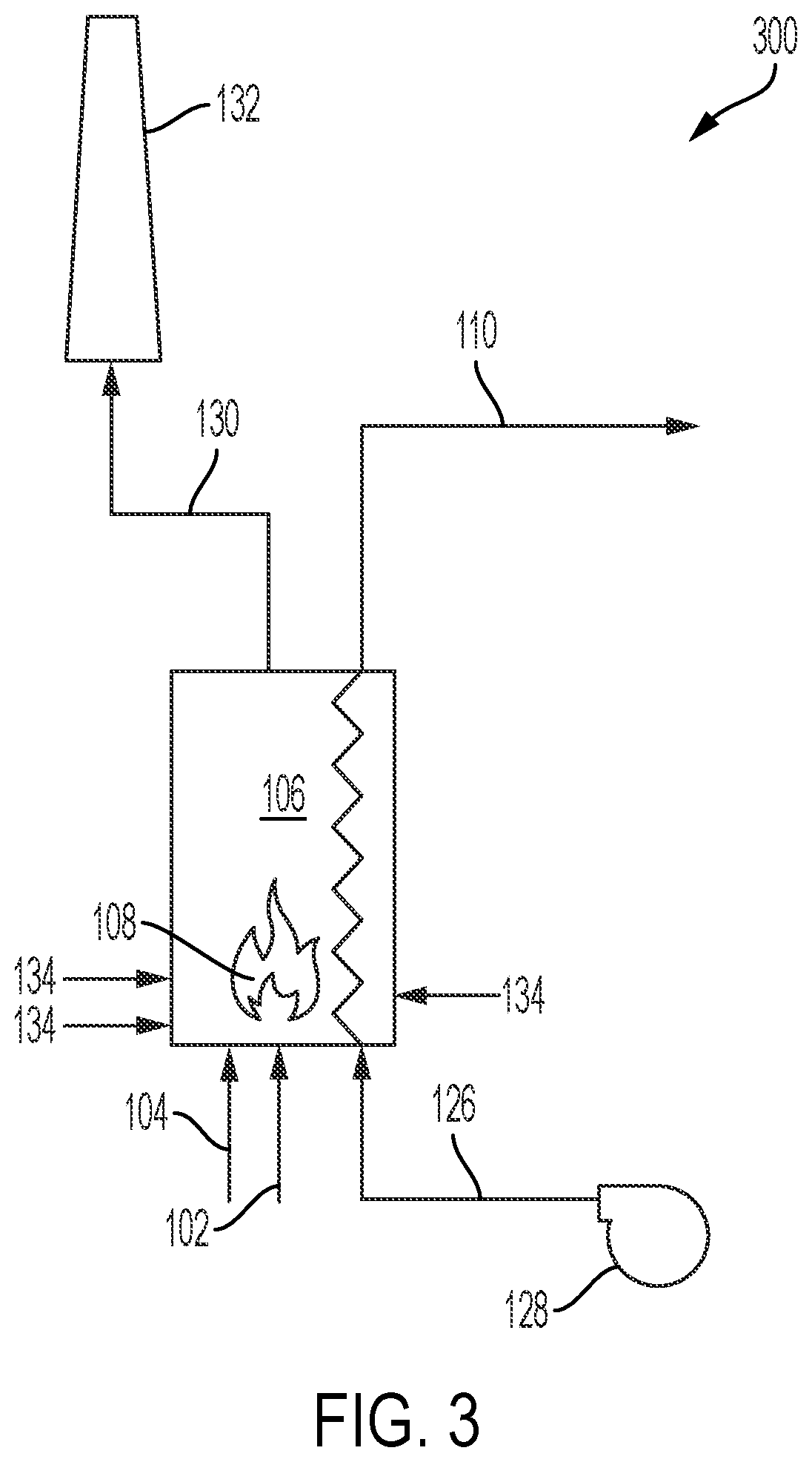
[0040]This invention relates generally to a system and process for electricity generation using steam production by hydrogen combustion, and more particularly to a Rankine Cycle system and process for the generation of electricity using pure hydrogen as a primary fuel source for the generation of steam in the boiler system. Pure hydrogen herein as used herein means hydrogen with a purity higher than 99%. The Rankine Cycle system and process may also use a mixture of hydrogen with one or more secondary fuels to reduce emissions of carbon dioxide. Addition...


PUM


Abstract

The invention relates to a system and process for electricity generation using steam production by hydrogen combustion, and more particularly to a Rankine Cycle system and process for the generation of electricity using a primary pure hydrogen fuel source for the generation of steam in the boiler system. The Rankine Cycle system and process may also use one or more secondary fuel sources in combination with the primary hydrogen fuel source to supplement the primary pure hydrogen fuel if necessary. Additionally, the inventive system and process can use a flame temperature reducing fluid for lowering bulk flame temperature of a burner in the boiler system to increase equipment life and decrease equipment failure. The inventive Rankine Cycle system and process reduce emissions of carbon dioxide, nitrogen oxides, and other greenhouse gases into the atmosphere, and reduce bulk flame temperatures to increase equipment life and decrease equipment failure.

Description

CROSS REFERENCE TO RELATED APPLICATIONS[0001]This application claims the benefit of U.S. Provisional Patent Application No. 63 / 047,336 filed on Jul. 2, 2020. This application incorporates the foregoing application by reference into this document as if fully set out at this point.BACKGROUND OF THE INVENTION1. Field of the Invention[0002]This invention relates generally to a system and process for electricity generation using steam production by hydrogen combustion.2. Description of the Related Art[0003]Concerns regarding the depletion of non-renewable energy sources in the middle of last century initiated a government and industry drive towards research, development, and implementation of renewable technologies, such as solar, wind, hydro-electric and geothermal energy. The availability of inexpensive carbon-based fuels, however, limited the wide implementation of renewable energy as it could not compete effectively with traditional fuels. Government grants and subsidies for renewabl...

Claims


Application Information

Patent Timeline
IPC IPC(8): F01K23/10F01K23/18F01K25/00F01K11/02
CPCF01K23/103F01K23/18F05D2220/76F01K11/02F01K25/005F22B1/003Y02P20/129
Inventor RUIZ, ROBERTO
Owner RUIZ ROBERTO
Learn More