Multi function spinning platform

a spinning platform and multi-functional technology, applied in the field of rotating platforms, can solve the problems of difficult control, bulky and difficult to carry, and the difficulty of active real-time sensing and detection while spinning, and achieve good and precise control over the flow rate over tim

Pending Publication Date: 2022-01-13
DANMARKS TEKNISKE UNIV
View PDF0 Cites 0 Cited by
  • Summary
  • Abstract
  • Description
  • Claims
  • Application Information

AI Technical Summary

Benefits of technology

[0063]FIG. 44 shows the linear part of the calibration curve shown in FIG. 32 providing a relation between the rotational frequency of the platform and the corresponding achieved flow rate through the culture chamber. Thus, the linear regime can be used to precisely control the flow rate through the culture chamber. The variation in the flow rate between different microfluidic platforms was around 10%, based on 3 different tested platforms. The variation of the flow rate over time for up to 72 hours was around 5%, which means that it is possible to achieve a good and precise control over the flow rate over time.

Problems solved by technology

However the LoD has its limitations, one of them being that it is hard to implement active, real-time sensing and detection while spinning.
A conventional spinning LoD system is typically driven by an external spindle motor which are both bulky and difficult to control.
Also the traditional strobe photography setup for imaging microfluidic channels in the disc, while the disc is spinning, is bulky and requires a dedicated setup.
These methods have defined protocols and standard procedures, but they do not mimic the real bacterial natural growth environment since the bacteria grows in static or in best condition on shaking plates.
Moreover, in these assays it is difficult to achieve biofilm formation and in addition they require several steps and sample handling increasing the possibilities to introduce error, invalidating the final result and decreasing the throughput.
Most of the fluidic systems require bulky and expensive pumps, tubes and actuators, which involve a large consumption of liquid and sample together with the need for trained personnel to operate the platform.
Furthermore, they often introduce bubbles in the flow chip damaging the culture.
However, there are no a lab-on-a-disc system that can facilitate long-term cultivation of bacteria or mammalian cells.

Method used


Image

  • Multi function spinning platform
  • Multi function spinning platform
  • Multi function spinning platform

Examples


examples

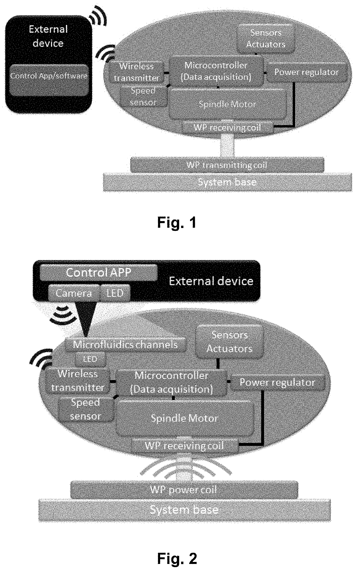
[0155]FIG. 7 shows a schematic illustration of an example of the presently disclosed powered lab-on-a-disc (PLoD) device: A miniaturized wireless optical microscope of the PLoD platform, which integrates a 2.4 GHz Wi-Fi transmitter, a complementary metal-oxide-semiconductor (CMOS, 1920×1080 pixels) sensor, with a high numerical aperture optics and a wireless inductive “Qi” energy transmission interface4. The motor is not show in FIG. 7. On the cell culture disc, cells are incubated in a cell culture chamber which is sealed by a lid layer. Cell clusters can be imaged by the CMOS sensor, while the real-time photo and video can be wirelessly displayed and stored on a smartphone or PC through the Wi-Fi transmitter. The Qi interface ensures stable power supply for the functioning of the wireless microscope for the full incubation period.

[0156]The wireless microscope imaging parameters such as resolution (1920×1080 / 1280×720), exposure time, modes switching (color / infrared) and photo / video...


PUM


Abstract

A rotatable platform is provided for use in Lab-on-disc (LoD) applications. A LoD microfluidic device has the rotatable platform and is suitable for analysis of a fluid sample. Real-time monitoring of cells is also provided, using a centrifugal microfluidic platform. A mobile LoD device is provided, which can be used in remote destinations and for point of care applications. A method for monitoring microorganisms under the constant supply of nutrients includes the step of inoculating the cells in a culture chamber in a rotatable microfluidic platform, rotating the platform such that liquid in a reservoir connected to or located on the platform, the liquid comprising nutrients for the cells, is constantly supplied to the cells in the culture chamber by means of shear/centrifugal force resulting from rotating the platform, and continuously monitoring the cells during rotation of the platform by means of imaging, electrochemical and/or electrical measurements.

Description

CROSS REFERENCE TO RELATED APPLICATION[0001]This application is the U.S. National Stage of PCT / EP2019 / 079115 filed Oct. 24, 2019, which claims priority to European Patent Application No. 18202261.6, filed Oct. 24, 2018, the entire content of both are incorporated herein by reference in their entirety.FIELD OF THE INVENTION[0002]The present disclosure relates to rotatable platform for use in Lab-on-disc (LoD) applications, and LoD microfluidic device having the rotatable platform and which is suitable for analysis of a fluid sample. The present disclosure further relates to real-time monitoring of cells using a centrifugal microfluidic platform. In particular, the present disclosure relates to a mobile LoD device, which can be used in remote destinations and for point of care applications.BACKGROUND OF INVENTION[0003]Lab on disc (LoD) techniques has existed for decades. The basic principle is a scaled-down system for studying centrifugal phenomena. LoD is beneficial for separation of...

Claims


Application Information

Patent Timeline
Patent Type & Authority Applications(United States)
IPC IPC(8): B01L3/00G01N27/27G01N27/327B04B5/12G01N21/65
CPCB01L3/502753B01L2400/0409G01N27/327B04B5/12G01N21/65B01L2200/027B01L2200/0642B01L2200/10B01L2200/18B01L2300/023B01L2300/0645B01L2300/0663B01L2300/0654B01L2300/0803B01L2300/12G01N27/27G01N35/00069G01N35/00871G01N2035/00237G01N2035/00356G01N2035/00881G01N2035/1034B01L3/502715B01L9/527B01L3/502761B01L3/50273B01L2300/0883
Inventor BOISEN, ANJAHWU, EN-TEZOR, KINGA IUDITHRANJENDRAN, SRIRAM THOPPESERIOLI, LAURA
Owner DANMARKS TEKNISKE UNIV
Why Eureka
Try Eureka