
Electric aircraft propulsion system

Active Publication Date: 2022-01-13
DUXION MOTORS INC
View PDF1 Cites 3 Cited by
  • Summary
  • Abstract
  • Description
  • Claims
  • Application Information

AI Technical Summary

Benefits of technology

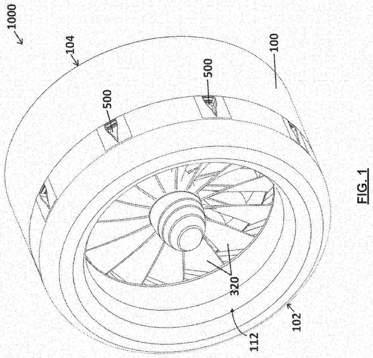
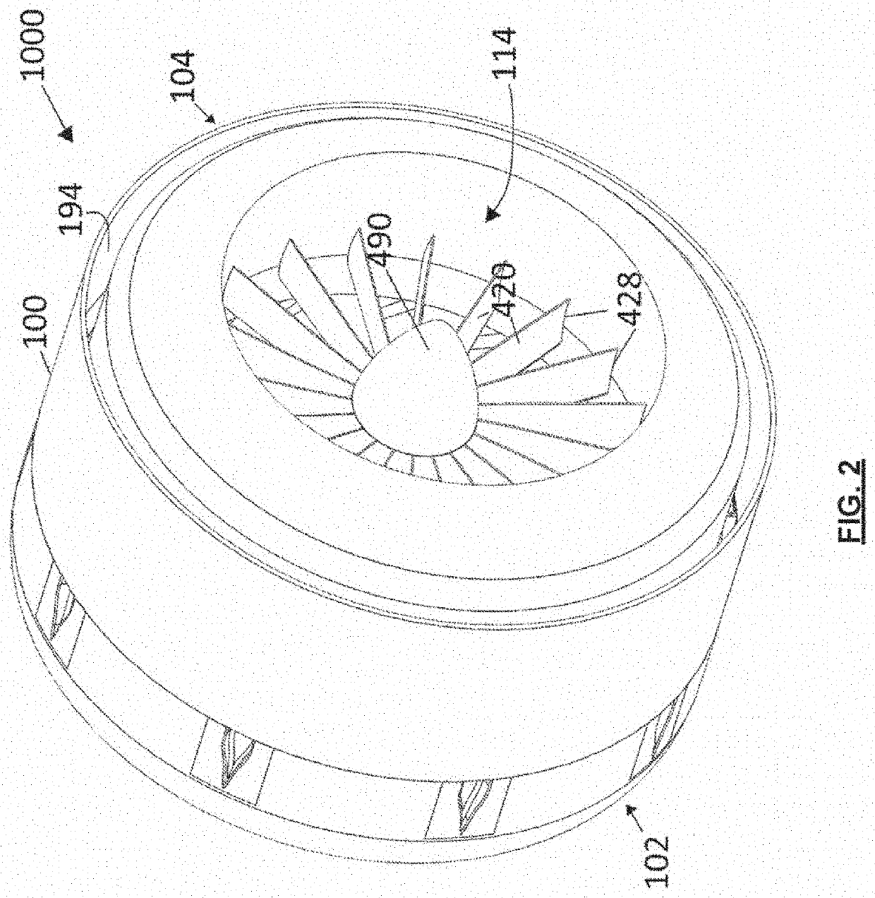
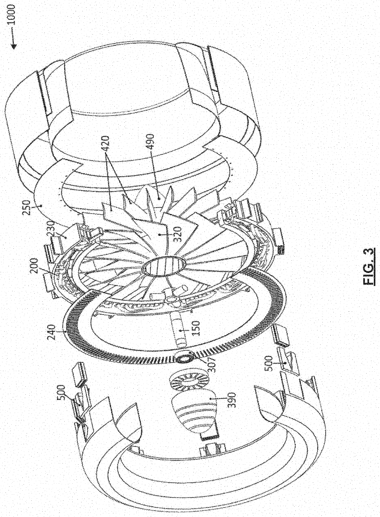
The electric aircraft propulsion system disclosed in this patent allows for more efficient and efficient propulsion by integrating ducted fan blades into an electric machine. This results in a high aspect ratio between the diameter and axial length of the electric machine, making it scalable for higher output power without reaching magnetic saturation. The propulsion fan blades are secured to both an inner hub and an outer shroud, and pre-loaded during manufacture or assembly to compensate for expected centrifugal forces and hoop stresses during high-speed operation. This results in less net tensile stress on the rotor and fan assembly and improved performance during high-speed operation.

Problems solved by technology

However, motors with higher power ratings tend to have larger outer diameters, which reduce propulsion efficiency when the motor is located inside the duct.
However, a larger motor and larger fan blades may significantly increase the weight of the propulsion system.
Further, as the size and weight of the propulsion system increases, the thrust-to-weight ratio for the system typically goes down.
Also, such a system may suffer from significantly increased vibrations, which may necessitate more frequent maintenance, increase vulnerability to mechanical failure, and / or generates higher levels of audible noise.

Method used


Image

  • Electric aircraft propulsion system
  • Electric aircraft propulsion system
  • Electric aircraft propulsion system

Examples


Embodiment Construction

[0087]Various apparatuses, methods and compositions are described below to provide an example of an embodiment of each claimed invention. No embodiment described below limits any claimed invention and any claimed invention may cover apparatuses and methods that differ from those described below. The claimed inventions are not limited to apparatuses, methods and compositions having all of the features of any one apparatus, method or composition described below or to features common to multiple or all of the apparatuses, methods or compositions described below. It is possible that an apparatus, method or composition described below is not an embodiment of any claimed invention. Any invention disclosed in an apparatus, method or composition described below that is not claimed in this document may be the subject matter of another protective instrument, for example, a continuing patent application, and the applicant(s), inventor(s) and / or owner(s) do not intend to abandon, disclaim, or d...


PUM


Abstract

An electric propulsion system for an aircraft includes a nacelle and an electric machine. The electric machine includes a stator positioned in the nacelle, and a rotor and fan assembly positioned in a primary flow path through the nacelle. The rotor and fan assembly includes a cylindrical fan shroud, a plurality of rotor magnets positioned on an outer surface of the fan shroud, and a fan hub mounted on a central support shaft via one or more bearings. A plurality of fan blades extend between an inner surface of the fan shroud and an outer surface of the fan hub. The rotor magnets may be loaded in compression in a radial direction when the rotor and fan assembly is at rest. The fan blades may be pre-stressed in a radial direction when the rotor and fan assembly is at rest.

Description

CROSS-REFERENCE TO RELATED APPLICATIONS[0001]This application is a Continuation in Part of U.S. patent application Ser. No. 16 / 989,117, filed Aug. 10, 2020, which issued on Jul. 13, 2021 as U.S. Pat. No. 11 / 059,599, which is a Continuation of International Application No. PCT / CA2020 / 050662, filed on May 15, 2020, which claims the benefit of U.S. Provisional Application No. 62 / 848,897, filed on May 16, 2019, the disclosures of which are incorporated herein by reference.FIELD[0002]This disclosure relates generally to propulsion systems for aircraft, and more specifically to direct drive electric ducted fan propulsion systems for aircraft.INTRODUCTION[0003]A conventional propulsion system for aircraft includes a motor that transmits torque through a rotating shaft to drive a propulsion fan to propel the aircraft. The rotating shaft is typically housed inside of or directly coupled to the motor.[0004]In the case of ducted fan propulsion systems, the motor is typically located inside the...

Claims


Application Information

Patent Timeline
IPC IPC(8): B64D27/24F04D19/00F04D25/06B64D29/00H02K5/18H02K5/20H02K7/14H02K9/20H02K21/14
CPCB64D27/24F04D19/002F04D25/06B64D29/00H02K21/14H02K5/207H02K7/14H02K9/20H02K5/18H02K9/227H02K9/225H02K3/24F04D25/066F04D29/326F04D19/024B64C11/001F04D29/5806B64D2241/00F04D19/026F04D27/0246F04D29/322Y02T50/40Y02T50/60
Inventor RABBI, SHEIKH FAZLEPILGRIM, RICK RALPHGENGE, KYLE REUBENFORWARD, TREVORKEATING, ADAMROPER, RICHARD ROBERTLOBO, BRYAN GABIN
Owner DUXION MOTORS INC
Learn More