Process for pvc-containing mixed plastic waste pyrolysis

a technology of mixed plastic waste and pyrolysis oil, which is applied in the direction of combustion types, lighting and heating apparatus, incinerator apparatus, etc. it can solve the problems of high cost, high cl level of products, and inability to meet the requirements of pyrolysis, so as to reduce the amount of adsorbent, enhance the fixation of chlorine, and reduce the level of products

Pending Publication Date: 2022-01-13
UOP LLC
View PDF6 Cites 4 Cited by
  • Summary
  • Abstract
  • Description
  • Claims
  • Application Information

AI Technical Summary

Benefits of technology

[0011]In accordance with another exemplary embodiment, a process for pyrolyzing a PVC containing feed while minimizing the amount of chloride in the product is provided. High chloride removal has been found to require a stepwise method to meet product specification requirements. It requires a minimum of two steps and may require three steps to achieve a low product Cl level. The first step of the dechlorination process comprises a partial conversion of polyvinyl chloride to hydrogen chloride in the melting step. The hydrogen chloride from this reaction is contained in the melting reactor vapor stream and is directly sent to the incinerator to burn off along with any hydrocarbon gas, and to possibly help provide heat for the pyrolysis reactor. Next, hydrogen chloride rich gas produced from pyrolysis reactor is further removed while liquid products is progressively condensed. Optionally, a finely ground solid sorbent is added to the reactor to enhance the fixation of chlorine by reacting sorbent with hydrogen chloride product. The solid sorbent is an alkaline rich and inexpensive reactant that reacts with residual chloride. Through condensing, hydrogen chloride rich is separated from main pyrolysis oil product. The condensed pyrolysis oil product is sent to a post treatment bed. A small bed of adsorbent further removes chloride content of the product to nearly zero percent. The synergy utilizing the stepwise approach to treat Cl from >5800 ppw in feed to 10 ppw in product with the processes and apparatuses described herein is previously unknown. The invention discloses a synergetic method for chloride removal, the first dechlorination tank size may be much smaller than main cracking reactor. The amount of adsorbent needed in these beds is minimized by the other steps described above. The final polishing chloride removal step is in economical using an adsorbent solution as part of this invention. The invention eliminates the need for extensive presorting at the feed end when a mixed plastic feed has a high PVC content, e.g. >1% wt. The invention achieves a low chlorine level in final pyrolysis oil product, such as <10 ppwm in product, or <6 ppm preferably that single technique may not achieve in a practical scale with the processes and apparatuses described.

Problems solved by technology

Non-plastics, e.g., metal, dirt and wood are obviously undesired.
Not all plastics are suitable to pyrolysis processing: PVC is particularly undesirable due to its chloride derivatives in products that may harm downstream process metallurgy if left untreated.
The sorting may be very complex and costly.
Without costly sorting steps to remove most PVC out before the pyrolysis unit, it is unlikely to treat chloride down to an acceptable level with prior art processes.
Any technology may not achieve 99.999% chloride removal efficiency in single step which is needed to handle 2% PVC in feed.
This results in a large temperature gradient in the reactor.
The net effect is excessive char deposit originating from the fluid near the hotter wall and poorer heat transfer as a result.
Such a heated system also limits the size of the pyrolysis process.
The circulating heat medium may thermally crack however, which creates complications with selection of the heating fluid.
The plastic itself also has a low thermal conductivity which means that a larger amount of heat medium may be required.
Crude oil and its distillation fractions are known to crack significantly at the temperatures seen in the pyrolysis reactor.
This poses a practical challenge when such a supply is difficult to obtain and adds extra cost to the process.

Method used


Image

  • Process for pvc-containing mixed plastic waste pyrolysis
  • Process for pvc-containing mixed plastic waste pyrolysis

Examples


example

Example 1

[0051]Chloride mass balance studies are presented. The calculation is based on experimental data collected for melt tank dechlorination, sorbent performance and adsorbent performance. An experiment done at 320° C., feed PVC 1%, 2% or 3%, product Cl<10 ppmw. Three steps are taken in series, showing melt tank size, sorbent use and adsorbent use. The example is scaled to 1 ton / year feed flow basis. The data shows that if only one single step of chloride removal is used, a very large reactor, or large sorbent use and adsorbent use are needed (see ratios of melt tank size to reactor size to the one in three steps in series). This Example explains how using three steps in series provides synergy as compared with any or two of the three steps.

I. Information inputsCa(OH)2 Molecular weight, g / moles747474CL Molecular weight, g / moles353535Feed flow t / hr, scaled111Study cases123Feed PVC, wt %136Feed PVC, kg / hr103060Cl in feed, ppmw56721701634032RX size, main reactor size is scaled as 1...

example 2

[0052]A recycle plastic stream was obtained from a Wisconsin material recovery facility. The compositions are 2% wt PVC, 20% PE, 75% PP, the remaining being PET, paper, organic residue, and metal species. Cl measured in feed is 1.189wt % Cl.[0053]Step 1: A 100 grams of the feed was batch pyrolysised in a 500 cc reactor under conditions of atmospheric pressure ˜25 psig. The reactor was heated from ambient condition to 300C. hold for 2 hours. After shutdown, the reactor content was solidified, recovered and measured (namely, first stage liquid product).[0054]Step 2. The same feed was tested identical testing conditions as step 1. After holding at 300C for 2 hours. The reactor continued to raise to 400° C., held for one hour. After cooled, the product produced out of the pyrolysis reaction was collected in an ice-cooled condenser. 67 grams of products were collected (namely, total pyrolysis product). A few runs were repeated as step 2 to accumulate ˜300 gm of liquid product (namely, co...

specific embodiments

[0056]While the following is described in conjunction with specific embodiments, it will be understood that this description is intended to illustrate and not limit the scope of the preceding description and the appended claims.

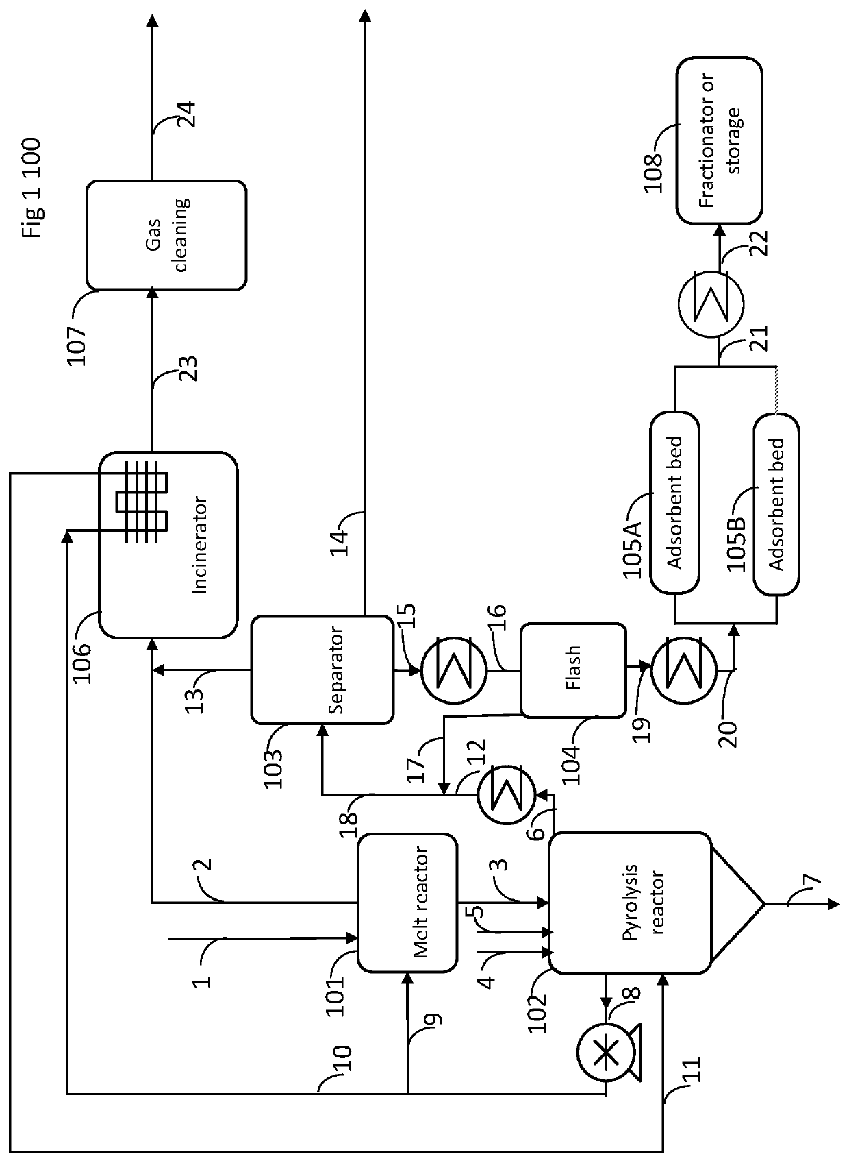
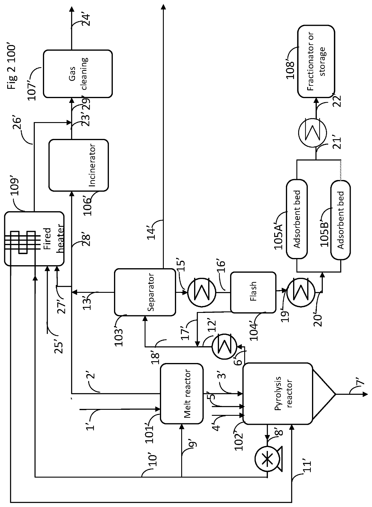
[0057]A first embodiment of the invention is a process for producing low-chloride pyrolysis oil out of a mixed plastic waste stream comprising three chloride removal steps operating in series; melting the mixed plastic waste stream with a hot product stream in a melting reactor to produce a melted mixed plastic waste stream comprising at least two types of plastic including chlorine-containing plastics and other plastics to produce a first chloride-rich vapor stream and a first liquid stream; sending the first liquid stream to a pyrolysis reactor to be heated with a hot product stream to produce a second chloride rich vapor stream, a second liquid stream and solid particles; adding a sorbent to the pyrolysis reactor to adsorb chloride containing molecules; se...


PUM

PropertyMeasurementUnit
temperatureaaaaaaaaaa

Abstract

A process for pyrolysis of a mixed plastic stream that contains polyvinyl chloride (PVC) is provided in which the chloride from PVC is removed from an initial melting reactor that heats the mixed plastic stream to a sufficient temperature to produce HCl but at a low enough temperature to avoid production of organochlorides. Chloride is primarily removed in a vapor stream from the initial melting reactor, while additional chloride removal may be removed downstream from the melting reactor by the use of sorbent addition to the pyrolysis reactor and by subsequent adsorbent beds.

Description

FIELD[0001]This application claims priority from provisional application 63 / 050704 filed on Jul. 10, 2020, which is incorporated herein in its entirety.[0002]The general field is the pyrolyzing of a plastic waste stream into hydrocarbons while minimizing the amount of mixed plastic sorting that is required. Particularly, the disclosure relates to production of valuable and upgradable pyrolysis oil that meets chloride quality specifications at downstream upgrading facilities.BACKGROUND OF THE INVENTION[0003]Mixed plastic waste originates from curbside waste collection of post-consumer plastic waste. Mixed plastic waste also comes from specific industrial sites e.g., construction, packaging and agricultural wastes that have a broad range of compositions. The waste recycling facility applies a sorting process to recover recyclable plastics. Mixed plastic waste is what is left after sorting. This is considered to be at the end of its life and is commonly sent landfill or incineration. C...

Claims


Application Information

Patent Timeline
Patent Type & Authority Applications(United States)
IPC IPC(8): C10B53/07B01D15/08C10G31/06F23G5/027
CPCC10B53/07B01D15/08C10G31/06C10G2300/1003B01D2257/204B01D2215/00F23G5/027F23G7/12F23G2201/30F23G2202/20F23G2209/28C10G1/10C10G1/002C10G25/003C10B49/14C10B57/08C10B57/06Y02P20/143
Inventor SUN, PINGTYSKA, JEFFREYMONTALBANO, JOSEPH A.
Owner UOP LLC
Why Eureka
Try Eureka