Energy And Environmental Optimisation Of A Facility Comprising At Least One Combustion Apparatus With Burner

a technology of energy and environmental optimization and combustion apparatus, which is applied in the direction of lighting and heating apparatus, combustion types, heating types, etc., can solve the problems of limited efficiency of combustion apparatus, inability to meet the consumption demand, and often out of sync with the production of electrical energy that they allow, so as to avoid gas transportation and energy losses due to the joule effect, the overall efficiency is high, and the effect of high efficiency

Pending Publication Date: 2022-02-24
BULANE
View PDF0 Cites 1 Cited by
  • Summary
  • Abstract
  • Description
  • Claims
  • Application Information

AI Technical Summary

Benefits of technology

[0030]In general, such a local system allows for a very high overall efficiency, due to the production of hydrogen, the production and recovery of oxygen, and due to the recovery of the thermal energy generated during the electrolysis reaction.
[0031]In addition, gas transport and energy losses due to the Joule effect are avoided.

Problems solved by technology

In particular, combustion apparatus have limited efficiency because they use mainly air as oxidant, with only a small part of molecular oxygen and the rest being predominantly nitrogen.
Their applications, particularly in homes, are currently limited in that the production of electrical energy that they allow is often out of sync with the consumption demand.
However, “Power-to-Gas” solutions are still not widely deployed today.
In particular, the current urban underground networks, such as city gas, are not always adapted to transport, in particular hydrogen, whether or not combined with city gas, in compressed form.
Moreover, combustion apparatus that are not connected to city gas networks cannot benefit from these “Power-to-Gas” solutions.
Furthermore, hydrogen production by electrolysis is accompanied by oxygen production that is not recovered.
This represents the loss of a significant part of the gases produced during the electrolysis operation.
Finally, a significant part of the electrical energy used in electrolysis is lost in the form of waste heat generation (Joule effect) and not recovered, which limits the overall efficiency of this operation.

Method used


Image

  • Energy And Environmental Optimisation Of A Facility Comprising At Least One Combustion Apparatus With Burner
  • Energy And Environmental Optimisation Of A Facility Comprising At Least One Combustion Apparatus With Burner
  • Energy And Environmental Optimisation Of A Facility Comprising At Least One Combustion Apparatus With Burner

Examples


Embodiment Construction

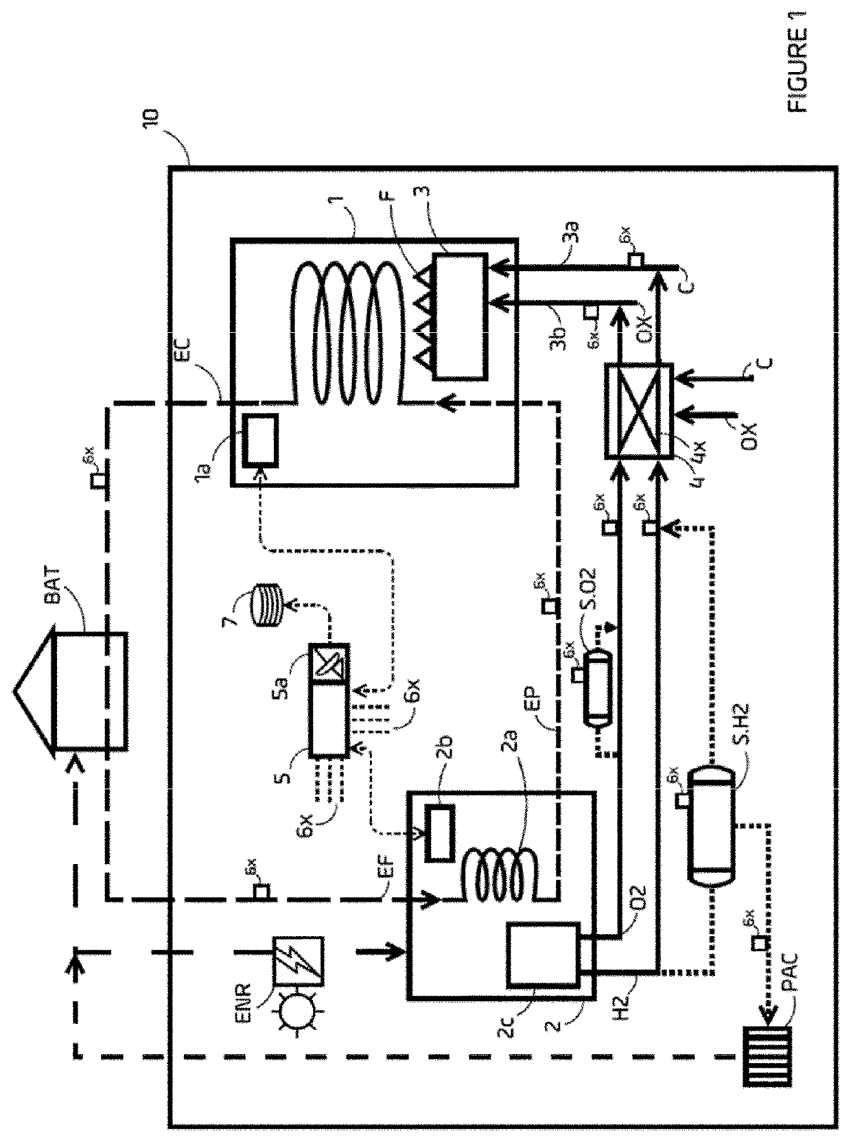
[0049]The facility shown in FIG. 1 comprises a combustion apparatus 1 and an electrolyzer 2.

[0050]The apparatus 1 has a burner 3 and can be of any type: boiler, ovens, etc. The facility of which it forms part can equip a building BAT, such as a single-family dwelling. Alternatively, the facility can be provided for a collective dwelling or for a company building.

[0051]In the example of FIG. 1, the combustion apparatus 1 is an individual boiler using liquid or gaseous fossil fuel C: domestic fuel oil, propane, butane, city gas, etc., and whose oxidant OX is air. It ensures the central heating of a dwelling BAT, the heating of a main hot water circuit or that of a secondary circuit.

[0052]Its burner 3 heats a heat-transfer fluid or a hot-water circuit EC-EF-EP.

[0053]The electrolyzer 2 can use several types of electrolysis technologies such as alkaline or proton-exchange membrane (PEM).

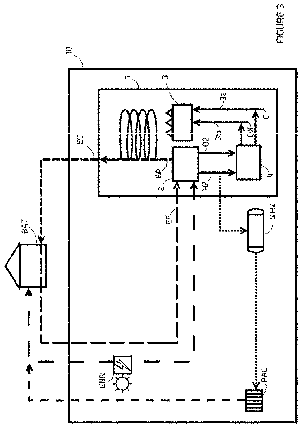
[0054]It can advantageously be integrated into the combustion apparatus 1, in order to simplify the el...


PUM

PropertyMeasurementUnit
poweraaaaaaaaaa
poweraaaaaaaaaa
energyaaaaaaaaaa

Abstract

The invention concerns a system for energy and environmental optimisation of a facility comprising at least one combustion apparatus (1) with a burner (3). The system comprises an electrolyser (2) and an injection system (4) connected to at least one fuel (3a) and/or oxidant (3b) inlet of the burner (3). The injection system is capable of injecting, at such an inlet, gases from the electrolyser (2) and/or a mixture of these gases and a combustible fluid and/or an oxidising fluid. The electrolyser (2) and/or the injection system (2) are controlled on the basis of at least one piece of information originating from the combustion apparatus (1) and/or sensors (6x) of the installation. The electrolyser can comprise a heat exchanger (2a) for cooling the device and/or preheating the water (EP) that is intended to then be heated (EC) by the combustion apparatus (1).

Description

GENERAL TECHNICAL FIELD AND PRIOR ART[0001]The present invention relates to a system for energy and environmental optimization of a facility comprising at least one combustion apparatus with burner.[0002]It is generally known that it is desirable to be able to improve the energy efficiency and the life span of equipment with burners (boilers, furnaces, etc.), in particular of those of individual or collective dwellings or of companies.[0003]In particular, combustion apparatus have limited efficiency because they use mainly air as oxidant, with only a small part of molecular oxygen and the rest being predominantly nitrogen.[0004]Furthermore, there is a desire to strongly reduce the emissions of greenhouse gases or other pollutants such as for example CO2, CO or nitrogen oxides (NOx), pollutants and toxic generated by this existing equipment which consumes air as oxidant.[0005]There is also a desire to reduce the dependence on and consumption of fossil fuels used to operate this equip...

Claims


Application Information

Patent Timeline
Patent Type & Authority Applications(United States)
IPC IPC(8): F23D14/32C25B1/04C25B15/02F23L7/00F23N1/02F24D3/00F24D18/00
CPCF23D14/32C25B1/04C25B15/02F23L7/007F23N1/022F24D3/005F23N2241/06F23L2900/07005F23L2900/07006F24D2200/19F24H2240/10F23N2237/08F23K2203/103F23C2900/9901Y02E20/34Y02E60/36F24D2101/30F24D2101/40F24D18/00F23K5/002F24H9/18F24H1/0027
Inventor JEREZ, NICOLASCHAMPSEIX, HENRI
Owner BULANE
Why Eureka
Try Eureka